


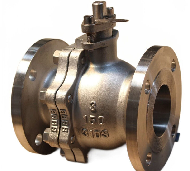
Welding Process for 310S Ball Valves: Methods, Materials, and Quality Control
Welding Process for 310S Ball Valves: A Practical Guide
1. Introduction
The welding process for 310S ball valves is an important consideration in manufacturing and fabrication applications that require high-temperature performance, oxidation resistance, and reliable mechanical integrity.
310S is a low-carbon, austenitic stainless steel containing high levels of chromium and nickel. It is commonly selected for components exposed to elevated temperatures, including industrial furnaces, thermal processing equipment, and high-temperature piping systems. The alloy can be welded using several conventional fusion welding methods, but appropriate filler metal selection, heat input control, joint preparation, and post-weld cleaning are essential for consistent results.
For manufacturers such as OUDIAN VALVOLA, a controlled welding process should consider not only weld integrity but also valve-body distortion, sealing performance, and the requirements of the final service environment.
2. Why Is Welding Quality Important for 310S Ball Valves?
A ball valve typically consists of a valve body, ball, stem, seats, seals, and an operating mechanism. Depending on its design, welding may be used to connect welded-end valves to pipelines, join body sections in fully welded constructions, or fabricate specific valve components.
The welding process must meet several objectives:
- Maintain structural integrity: The weld must meet the specified mechanical and fabrication requirements.
- Protect high-temperature performance: Excessive oxidation and unsuitable welding procedures can affect the properties of the weld and heat-affected zone.
- Reduce hot-cracking risk: Highly alloyed austenitic weld metal can be susceptible to solidification cracking under unfavorable conditions.
- Control distortion: Uneven heating and cooling can affect body alignment and critical dimensions.
- Protect valve sealing components: Excessive heat transfer to seats, seals, and other internal components can compromise their function.
The appropriate procedure depends on whether the work involves welding 310S components to one another, welding dissimilar materials, repairing a casting, or joining a valve to a pipeline. These operations should not automatically use the same welding procedure.
3. Common Welding Methods for 310S Ball Valves
• TIG Welding (GTAW – Gas Tungsten Arc Welding): The most widely used method for 310S ball valves. It provides high precision, strict control over heat input, and clean welds essential for thin-walled or high-purity stainless steel configurations.
• MIG / GMAW (Gas Metal Arc Welding): Utilized with short-arc or pulsed settings to reduce heat build-up, though it requires careful parameter control to prevent overheating the valve body.
• Short Arc / Pulsed Arc Welding: Specialized low-heat transfer modes used to minimize thermal distortion and protect the integrity of the 310S material structure.
3.1 TIG Welding (GTAW)
Tungsten Inert Gas (TIG) welding, also known as Gas Tungsten Arc Welding (GTAW), is suitable for precision welding and root passes where good control of the weld pool is important.
Vantaggi:
- Precise control of the welding arc and weld pool.
- Good weld appearance and clean weld formation when correctly performed.
- Suitable for thin sections, root passes, and selected precision fabrication work.
- Can provide high-quality welds when joint preparation and shielding are properly controlled.
TIG welding is often a practical choice for smaller components, thin-wall sections, and applications where root quality is critical.
3.2 MIG Welding (GMAW)
Metal Inert Gas (MIG) welding, generally classified as Gas Metal Arc Welding (GMAW), can be suitable for production welding where higher deposition rates are required.
Its suitability depends on material thickness, joint geometry, welding position, shielding gas, filler metal, and the approved welding procedure. Parameters must be established through a qualified procedure rather than selected solely to maximize welding speed.
3.3 Shielded Metal Arc Welding (SMAW)
Shielded Metal Arc Welding, or stick welding, is commonly used for fabrication and repair work where portability and equipment flexibility are important.
A suitable electrode designed for the specified alloy combination must be selected. Electrode storage, handling, and welding technique should follow the consumable manufacturer’s instructions and the approved procedure.
3.4 Submerged Arc Welding (SAW)
Submerged Arc Welding may be appropriate for larger or thicker fabrication assemblies where the joint design and production conditions support mechanized welding.
It is generally less suitable for small, intricate valve components where access, dimensional control, and localized heat input are major concerns.
All four methods can be used for appropriate 310S welding applications, provided the process and procedure are qualified for the actual joint and service requirements. <Cite refs={[“turn692915search3″,”turn220039search0”]} />
4. Selecting Filler Metal for 310S Stainless Steel
Filler metal selection is one of the most important decisions in the welding process.
For welding 310S to 310S, ER310 filler metal or an appropriate E310-class electrode may be considered when a matching weld-metal composition is required. The final selection must account for the base-metal specification, service temperature, joint design, mechanical requirements, and applicable welding code.
For dissimilar-metal joints, the correct filler may be different. A filler suitable for joining 310S to another stainless steel or to carbon steel should not be selected solely because it is commonly used for stainless steel.
Before production welding, verify:
- Base-metal grade and material certificates.
- Filler-metal classification and manufacturer documentation.
- Compatibility with the design temperature and process medium.
- Required mechanical properties and corrosion or oxidation resistance.
- Welding procedure qualification requirements.
For elevated-temperature applications, the weld metal’s performance at service temperature deserves particular attention. The most suitable filler is the one qualified for the actual joint and operating conditions, not necessarily the one that produces the easiest-looking weld.
5. Welding Preparation Before Production
Proper preparation helps prevent porosity, inclusions, lack of fusion, and contamination.
Step 1: Verify the Materials
Confirm that the components are the specified 310S grade and that all dissimilar materials are correctly identified. Review the material certificates and the approved fabrication drawings before welding.
Step 2: Prepare the Joint
Machine or grind the weld groove according to the approved drawing and welding procedure. Remove oxide scale, oil, grease, moisture, paint, and other contaminants from the joint and adjacent surfaces.
Use dedicated stainless steel cleaning tools to reduce the risk of carbon-steel contamination.
Step 3: Check Alignment and Fit-Up
Verify root gap, groove geometry, component alignment, and dimensional tolerances. For ball valves, maintain the specified geometry of the body and welded ends to reduce the risk of distortion affecting assembly or operation.
Step 4: Confirm Equipment and Consumables
Check the welding machine, cables, gas supply, filler materials, and relevant measuring equipment. Ensure that the shielding arrangement is appropriate for the joint, especially where full penetration and internal weld-root quality are required.
Step 5: Review the Welding Procedure
The Welding Procedure Specification (WPS) should define the applicable process, filler metal, welding parameters, joint preparation, preheat requirements where applicable, interpass-temperature limits, and any required post-weld treatment or examination.
6. Heat Input and Interpass Temperature Control
310S has a high alloy content and can be susceptible to weld-metal hot cracking under unfavorable solidification and restraint conditions. Excessive heat input can also contribute to distortion and unnecessary exposure of the heat-affected zone to elevated temperatures.
A controlled procedure should address:
- Welding current and voltage.
- Travel speed and heat input.
- Interpass temperature during multi-pass welding.
- Weld sequence and restraint.
- Cooling between passes.
- Protection of internal valve components from excessive heat.
Some technical guidance for highly alloyed austenitic heat-resistant stainless steels recommends relatively low heat input and interpass temperatures around 100–125°C, depending on section thickness and joint configuration. This is a general reference, not a universal acceptance limit for every 310S ball valve. The applicable limits must be established by the approved WPS and relevant code.
Preheating and post-weld heat treatment should not be applied automatically. Their necessity depends on the material specification, joint, service requirements, and governing procedure.
7. Welding Precautions for Ball Valve Assemblies
Welding a valve requires additional care compared with welding a simple plate or pipe coupon because valve geometry and internal components may be sensitive to heat.
7.1 Protect Seats and Seals
Soft seats, elastomeric seals, and other temperature-sensitive components can be damaged by welding heat. Where the design permits, follow the manufacturer’s instructions for disassembly, component removal, or other approved thermal-protection measures.
Do not assume that a particular seat material can withstand the welding temperature simply because the valve body is made from 310S.
7.2 Minimize Body Distortion
Use the specified fit-up, fixtures, and welding sequence. Where appropriate, balanced welding and controlled multi-pass deposition can help reduce uneven shrinkage.
After welding, check critical dimensions and verify that the ball, stem, and operating mechanism function as required by the design.
7.3 Maintain Cleanliness
Prevent grinding dust, weld spatter, and other debris from entering the valve cavity. Foreign material can damage sealing surfaces or interfere with smooth valve operation.
7.4 Follow the Correct Sequence
The welding sequence should be planned around the valve construction. For fully welded ball valves, body welding may need to be coordinated with internal component installation and thermal protection. For welded-end valves, the manufacturer’s installation instructions should govern welding to the pipeline.
Important: Welding a 310S valve body, joining a fully welded valve assembly, and welding the valve to a pipeline are different operations. Each requires an appropriate procedure and inspection plan.
8. Post-Weld Cleaning and Surface Treatment
Welding can produce heat tint and oxide scale on stainless steel. These surface oxides may affect corrosion resistance and oxidation performance, depending on the service environment.
Post-weld treatment may include:
- Removing slag and spatter.
- Cleaning the weld and adjacent surfaces with dedicated stainless steel tools.
- Removing heat tint and oxide scale using an approved mechanical or chemical method.
- Rinsing thoroughly after chemical treatment, where applicable.
- Inspecting the cleaned surface for cracks, undercut, porosity, and other visible defects.
Pickling chemicals, particularly those containing hydrofluoric acid, require specialized controls and trained personnel. Use only approved products and follow the relevant safety procedures.
The final surface-treatment requirements should reflect whether the valve will operate in a high-temperature gas environment, a corrosive liquid, or another service condition.
9. Inspection and Quality Control
A complete quality-control plan should be based on the valve specification, purchase requirements, applicable welding code, and approved inspection and test plan.
| Inspection item | Purpose |
|---|---|
| Visual testing (VT) | Check weld appearance, profile, and visible discontinuities |
| Dimensional inspection | Verify alignment and critical valve-body dimensions |
| Liquid penetrant testing (PT) | Detect surface-breaking discontinuities where required |
| Radiographic testing (RT) or ultrasonic testing (UT) | Examine weld integrity where required by the governing specification and joint geometry |
| Material and consumable traceability | Confirm the specified base material and filler metal |
| Pressure and seat-leakage testing | Verify valve pressure-boundary integrity and sealing performance under the specified test procedure |
| Functional testing | Confirm smooth opening and closing and correct assembly operation |
Not every valve requires every examination method. The applicable method, coverage, acceptance criteria, and test pressure must be defined by the governing standard and customer specification.
Weld repairs should be controlled by an approved repair procedure, followed by the required re-examination and testing.
10. Common Welding Defects and Prevention
| Potential defect | Possible cause | Preventive measure |
|---|---|---|
| Hot cracking | Unsuitable weld-metal composition, excessive restraint, or unfavorable welding conditions | Select qualified filler metal and control heat input and joint restraint |
| Porosity | Contaminated surfaces or inadequate shielding | Clean the joint and maintain suitable shielding conditions |
| Lack of fusion | Incorrect parameters, poor access, or unsuitable welding technique | Verify groove preparation and use qualified welding parameters |
| Excessive oxidation | Inadequate shielding or excessive heat exposure | Improve shielding and control the welding sequence |
| Distortion | Uneven heat input and weld shrinkage | Use appropriate fixtures, fit-up, and welding sequence |
| Damage to seats or seals | Excessive heat transfer during welding | Follow the valve manufacturer’s thermal-protection and assembly instructions |
Defect prevention begins with a qualified procedure, trained welders, clean materials, and consistent process monitoring.
11. Applications of 310S Ball Valves
310S stainless steel may be considered for ball valves used in selected high-temperature industrial applications, including:
- Furnace and heat-treatment equipment.
- Thermal processing and industrial heating systems.
- High-temperature gas-handling lines.
- Selected chemical and petrochemical process systems.
- Equipment exposed to elevated temperatures and oxidizing environments.
Actual suitability depends on temperature, pressure, medium composition, thermal cycling, valve design, seat material, and the manufacturer’s rating. The alloy’s high-temperature oxidation resistance does not automatically establish suitability for every corrosive chemical or pressure condition.
12. Frequently Asked Questions
Q1: Which welding method is best for 310S ball valves?
TIG/GTAW is often suitable for precision welding and root passes. MIG/GMAW, SMAW, or SAW may be appropriate for other production conditions. The best method depends on component thickness, joint design, access, productivity requirements, and the qualified welding procedure.
Q2: Which filler metal is used for 310S stainless steel?
ER310 or an E310-class electrode may be suitable for matching 310S base materials. Dissimilar-metal joints may require a different filler. Always verify the selection against the approved WPS and service requirements.
Q3: Does 310S require preheating before welding?
Preheating is generally not automatically required for 310S, but the final requirement depends on the approved procedure, component condition, ambient conditions, and applicable code. Follow the qualified WPS rather than a generic temperature recommendation.
Q4: Is post-weld heat treatment always necessary?
No. Post-weld heat treatment is not automatically required for every 310S weld. Some applications may specify solution annealing or another treatment to meet particular metallurgical or service requirements. Confirm the requirement before production.
Q5: How can weld quality be verified?
Quality verification may include visual and dimensional inspection, specified nondestructive examination, material traceability, pressure testing, seat-leakage testing, and functional testing. The inspection plan should define the required scope and acceptance criteria.
Q6: Can 310S ball valves be used at any high temperature?
No. The maximum allowable operating temperature depends on the complete valve design, pressure rating, seat and seal materials, process medium, and thermal cycling. Consult the manufacturer’s technical documentation for the specific model.
13. Conclusion
The welding process for 310S ball valves requires careful control of filler metal selection, joint preparation, heat input, interpass temperature, surface cleaning, and inspection. Because ball valves contain precision sealing and operating components, the welding procedure must also address distortion and thermal protection.
For reliable manufacturing, use a qualified WPS, appropriately trained welders, traceable materials, and an inspection plan that meets the applicable standards and project requirements.
VALVOLA OUDIANA supports industrial valve selection for a range of process applications. For a 310S ball valve inquiry, confirm the required size, pressure rating, end connection, operating temperature, process medium, and applicable design standard so that the valve configuration can be evaluated for the intended service.