


International Valve Leakage Testing Standards – A Comparison
Choosing the correct standard depends on the valve construction, the seating material, whether the device operates for throttling control or positive isolation, and the acceptable operational risk of the process piping system.
Valve Testing and Acceptable Leakage Rates Overview
Valve specifications previously relied heavily on Cold Working Pressure (CWP) ratings to define allowable operational limits and testing boundaries. A standard CWP designation, such as 800 PSI WOG, identified a valve rated for 800 PSI working pressure in cold water, oil, or gas service. Modern steel valve manufacturing has largely transitioned from legacy CWP designations to standardised ASME/ANSI pressure classifications, although CWP WOG ratings remain common for low-pressure threaded valves up to 2000 PSI.
Steel valve inspection and pressure testing widely adhere to API 598, officially titled the Valve Inspection & Test standard. This standard establishes specific leakage allowances for metal-seated valves exceeding nominal pipe size DN 50 (2 inches), whilst enforcing zero visible leakage for resilient soft seats. In contrast, MSS SP-61 provides testing procedures primarily applied to steel and bronze valves, covering gate, globe, and check configurations across commercial and industrial installations.
Pipeline transport applications require distinct manufacturing and testing specifications governed by API 6D. This pipeline standard addresses trunnion-mounted ball valves, pressure-balanced lubricated plug valves, and pipeline slab gate valves. Unlike general refinery standards, API 6D imposes zero leakage during seating closure tests for resilient-seated designs, enabled by resilient sealing systems. Aside from full-port swing check valves in API 6D, globe and check valves lack dedicated API production standards, prompting manufacturers to construct globe valves to BS 1873 and check valves to BS 1868, tested against API 598.
| Standard | Valve Types | Testing Focus | Seat Acceptance Criteria |
| API598 | Gate, Globe, Check | Refinery Isolation | Zero leakage on soft seats with defined allowances on metal seats. |
| API 6D | Pipeline Ball, Gate | Transmission Lines | Zero leakage for resilient seats using ISO 5208 Rate A criteria. |
| MSS SP-61 | Steel and Bronze | Commercial Valves | Prescribed liquid and gas closure limits based on seat diameter. |
| BS 1873 | Steel Globe Valves | Petrochemical Service | Tested to API 598 closure requirements with wall thickness checks. |
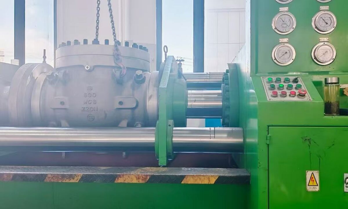
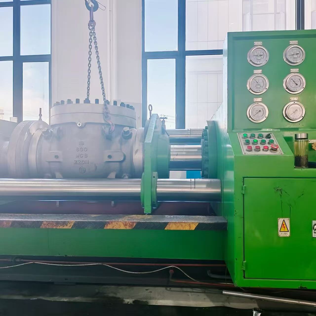
Pressure testing benches verify seat integrity and body shell strength against international reference standards.
Explanation of Zero and Low Leakage Test Standards
Specifications governing resilient, soft-seated valves, such as API 598 and MSS SP-61, define zero leakage as the absence of visible air bubbles or water droplets during designated test intervals. While commonly termed bubble-tight or zero leakage in commercial documentation, absolute containment at the atomic level remains unattainable. Minute quantities of fugitive process fluid can migrate past polymeric microstructures and mechanical packing interfaces, particularly when pressurised with low-molecular-weight gases such as helium or hydrogen.
Control valves operate under a separate leakage philosophy codified in ANSI/FCI 70-2, formerly known as ANSI B16.104. The most stringent category under this system, Class VI, applies to resilient-seated control valves designed for tight shut-off. Unlike isolation standards that require complete liquid drop and air bubble containment, FCI 70-2 Class VI permits a calculated quantity of gas bubbles per minute that scales upward with nominal valve size.
European and international pressure standards harmonise these definitions under ISO 5208 and EN 12266-1, which supersede the historical British Standard BS 6755-1. ISO 5208 classifies seat tightness into distinct categories from Rate A through Rate G. Rate A specifies no detectable leakage during the test window, aligning directly with API 598 requirements for soft-seated valves, while subsequent rate letters permit graduated leakage volumes for metallic seats.
Technical specifications must distinguish between resilient isolation valves requiring zero visible leakage under API 598 or ISO 5208 Rate A, and resilient control valves rated under FCI 70-2 Class VI, which allows a nominal bubble count during low-pressure pneumatic testing.
Pneumatic seat immersion testing measures leakage via calibrated liquid displacement or bubble detection.
ANSI/FCI 70-2 Valve Leakage Classifications
The ANSI/FCI 70-2 standard defines six discrete leakage classifications tailored for control valves. Because control valves prioritise dynamic flow modulation over absolute mechanical isolation, allowable leakage rates reflect the internal geometry, balancing seals, and actuator thrust available during process shut-off. Each classification establishes distinct test fluids, differential test pressures, and permissible flow rates past the closed plug and seat ring.
Class I mirrors the construction standards of Classes II, III, and IV but waives formal factory shop testing requirements. Class II targets double-port or balanced single-port valves utilising metal piston ring seals and metal-to-metal seats, permitting a leakage rate of 0.5 percent of the full rated valve capacity under air or water test pressures ranging from 45 to 60 PSI. Class III covers identical mechanical styles but tightens the permissible flow limit to 0.1 percent of rated capacity.
Class IV addresses single-port and balanced valves fitted with tight metal-to-metal seating and graphite or elastomeric piston seals. This class permits a maximum leakage rate of 0.01 percent of rated flow capacity under 45 to 60 PSI air or water pressure, representing the baseline for general industrial metal-seated control valves. Class V elevates testing requirements by mandating water at either 100 PSI or the valve operating differential pressure, restricting leakage to 0.0005 millilitres per minute per inch of port diameter per PSI differential pressure.
Class VI serves as the soft seat classification for resilient-seated control valves, using air or nitrogen gas at 50 PSI or the maximum service drop. Allowable leakage under Class VI remains exceptionally small, starting at 0.15 millilitres per minute for a 1-inch valve and extending to 11.5 millilitres per minute for a 12-inch valve. Although engineered specifically for modulating control valves, Class VI is occasionally referenced in piping specifications for metal-seated isolation butterfly and ball valves requiring superior closure.
| Class | Test Media | Pressure Range | Maximum Allowable Leakage |
| Class I | None Required | Not Specified | No shop test required by the standard. |
| Class II | Water or Air | 45 to 60 PSI | 0.5 percent of rated full valve capacity. |
| Class III | Water or Air | 45 to 60 PSI | 0.1 percent of rated full valve capacity. |
| Class IV | Water or Air | 45 to 60 PSI | 0.01 percent of rated full valve capacity. |
| Class V | Clean Water | 100 PSI or Drop | 0.0005 ml per min per inch port per PSI. |
| Class VI | Air or Nitrogen | 50 PSI or Drop | 0.15 to 11.5 ml per min based on valve size. |
Control valves classified under ANSI/FCI 70-2 require balancing dynamic control accuracy with seat leakage limits.
API 598 Valve Leakage Rates and Inspection Methods
API598 provides mandatory inspection parameters for gate, globe, plug, check, floating ball, and butterfly valves across petroleum refining and chemical processing industries. The standard mandates hydrostatic shell testing at 1.5 times the maximum cold working pressure and backseat testing for gate and globe valves to confirm structural containment. During shell and backseat evaluations, no structural weeping, packing seepage, or joint leakage is permitted on exterior surfaces.
Seat leakage limits under API598 distinguish between resilient soft seats, all-metal seats in isolation valves, and metal-to-metal check valves. Resilient-seated valves must exhibit zero drops of liquid and zero bubbles of gas throughout the designated testing duration. For metal-seated valves larger than DN 50 (2 inches), API 598 permits a defined rate of liquid drops or gas bubbles per minute, calculated relative to nominal diameter.
Pressure test configurations vary based on valve size and pressure class rating. For valves up to DN 100 (NPS 4) in ASME Class 1500 and valves exceeding DN 100 in ASME Class 600, specific combinations of low-pressure pneumatic closure and high-pressure hydrostatic closure are assigned. Lubricated plug valves and double block and bleed designs require mandatory high-pressure closure testing, whereas standard resilient-seated valves avoid repeated high-pressure testing that could distort soft elastomeric inserts.
While API 598 sets explicit allowable leakage thresholds, high-pressure hydrostatic seat tests and low-pressure pneumatic seat tests are optional for certain valve styles unless explicitly specified in the purchase requisition.
Hydrostatic shell tests verify pressure boundary containment before internal seat closure testing proceeds.
MSS SP-61 Valve Leakage Rates
Published by the Manufacturers Standardisation Society, MSS SP-61 outlines pressure testing requirements for steel valves in utility, chemical, and general industrial service. Section 5 of the standard outlines testing criteria for metal-seated gate, globe, angle, check, and butterfly valves. The testing regimen applies hydrostatic shell testing at 1.5 times the 100°F rating and seat closure testing at 1.1 times the maximum cold working pressure.
Under MSS SP-61, seat leakage criteria reflect the mechanical characteristics of precision metal-to-metal seating surfaces:
- Gate, globe, and butterfly valves allow a maximum hydrostatic seat leakage rate of 10 millilitres per hour per inch of nominal pipe diameter.
- Gas closure testing allows approximately 0.1 standard cubic feet of air per hour per inch of nominal pipe size under specified pneumatic test pressures.
- Resilient soft seats must achieve complete zero leakage during hydrostatic and pneumatic seat tests without visible droplets or bubble formation.
- Check valves do not require a formal factory seat test under baseline MSS SP-61 procedures, though manufacturers frequently test them to agreed client thresholds.
MSS SP-61 testing proves particularly common for forged steel gate and globe valves conforming to ASME B16.34. The standard bridges the gap between commercial manufacturing efficiency and rigorous process safety in power generation and steam distribution systems.
API 6D and ISO 5208 Pipeline Valve Leakage Rates
API 6D directly incorporates the leakage rate classifications defined in ISO 5208, aligning pipeline valve testing with international standard ISO 14313. These criteria govern high-integrity isolation equipment installed along cross-country natural gas, crude oil, and refined product transmission lines. The standard requires a hydrostatic shell test at 1.5 times cold working pressure, a hydrostatic seat test at 1.1 times cold working pressure, and a pneumatic low-pressure closure test.
ISO 5208 defines leakage severity across alphabetical tiers ranging from Rate A through Rate G, scaled per millimetre of nominal seat diameter per second. Rate A represents the absolute baseline for pipeline-style slab gate valves, lubricated plug valves, and soft-seated ball valves, mandating no visible leakage during the test window. Metal-seated pipeline valves typically conform to Rate D, which allows controlled liquid or gas seepage proportional to valve diameter.
Rate A Alignment
Applies to soft-seated pipeline valves and lubricated plug valves, demanding zero detectable drops or bubbles under both liquid and gas testing.
Rate D Criteria
Standard designation for metal-seated pipeline isolation valves, defining proportional liquid leakage under high-pressure hydrostatic closure tests.
Special Gas Testing
High-pressure pneumatic testing with nitrogen or helium treated as supplementary testing requiring dedicated blast protection and client approval.
The transition from legacy British Standard BS 6755-1 to ISO 5208 and EN 12266-1 harmonised these leakage definitions across European and American engineering contracts. This standardisation simplifies multi-jurisdictional procurement for pipeline operators.

API 6D pipeline valves undergo rigorous hydrostatic seat testing to verify pipeline containment.
Variations in Basic Test Parameters Across Standards
Comparing leakage standards requires evaluating the test media, pressures, and environmental controls stipulated by each testing code. Discrepancies in pneumatic pressure, water purity, and fluid temperature can alter observed leakage rates across identical physical valve assemblies. Engineering documentation must identify these baseline differences to prevent false passes or unrepresentative seal degradation during shop testing.
Gas pressure parameters vary between testing standards. ASME B16.34 specifies a gas closure test pressure of at least 80 PSI, whereas MSS SP-61 permits a test pressure range between 60 and 100 PSI. ISO 5208 and API 6D establish a standardised pneumatic closure pressure of 6 bar plus or minus 1 bar, translating to an operational range of 73 to 102 PSI.
Water chemistry represents another critical testing parameter, especially when inspecting corrosion-sensitive stainless steels. API 598 restricts chloride content in hydrostatic test water to 100 parts per million for austenitic stainless steel components. API 6D imposes an even stricter threshold, limiting chlorides to 30 parts per million on wetted surfaces of austenitic and duplex stainless steel valves to prevent stress corrosion cracking. Test fluid temperatures also vary, with ASME B16.34 setting a maximum limit of 125°F, while ISO 5208 and API 6D require testing between 41°F and 106°F.
| Standard | Gas Test Pressure | Chloride Limit | Intervallo di temperatura |
| ASME B16.34 | 80 PSI Minimum | Not Specified | Up to 125°F maximum test fluid temperature. |
| API598 | 80 to 100 PSI | 100 ppm max | Ambient factory conditions unless agreed. |
| MSS SP-61 | 60 to 100 PSI | Not Specified | Fluid temperature below 125°F maximum. |
| ISO 5208 | 73 to 102 PSI | Refer to client | Controlled range between 41°F and 106°F. |
| API 6D | 73 to 102 PSI | 30 ppm max | Controlled range between 41°F and 106°F. |
Leakage Comparison for Metal and Soft Seats
Selecting between metal and resilient seat designs involves balancing chemical compatibility, operational temperatures, and acceptable seat leakage thresholds. Resilient seating incorporates polymers such as PTFE, reinforced PTFE, PEEK, or elastomers such as FKM and EPDM. These materials deform elastically under mechanical load, sealing microscopic surface imperfections across the mating closure element to deliver bubble-tight isolation.
Metal seating relies on ground, lapped, and hardened metallic alloys such as Stellite, 316 stainless steel, or nickel alloys. Because metal faces cannot deform elastically to fill micro-voids, microscopic gaps persist through which test fluids can migrate under pressure. Standards accommodate these physical realities by defining acceptable drop and bubble frequencies for metal-to-metal contact.
Resilient Soft Seats
- Complies with API 598 zero visible leakage and ISO 5208 Rate A.
- Achieves bubble-tight closure under low-pressure gas testing.
- Limited by polymer degradation in severe high-temperature service.
- FCI 70-2 Class VI restricts leakage to minute millilitre limits.
Hardened Metal Seats
- Complies with API 598 metal seat tables and ISO 5208 Rate D.
- Permits measured droplet or bubble leakage during closure tests.
- Withstands severe temperatures, abrasive slurry, and thermal cycling.
- Frequently specified to FCI 70-2 Class IV or Class V limits.
For valves ranging from 2 inches (DN 50) to 40 inches (DN 1000), allowable metal-seated leakage scales proportionally with diameter under API 598. In critical hydrocarbon services, metal-seated isolation valves can be specified to meet FCI 70-2 Class V or VI, requiring precision grinding and higher actuator seating torque.
Machined metal sealing surfaces and resilient polymer inserts require distinct leakage evaluation criteria.
Selecting the Appropriate Leakage Standard for Industrial Applications
Specifying the proper valve leakage standard requires matching process safety requirements with mechanical valve capability. Imposing zero leakage standards on high-temperature, metal-seated gate valves introduces extreme manufacturing complexity and unwarranted cost. Conversely, applying control valve standards such as FCI 70-2 Class IV to hazardous chemical isolation points creates potential environmental and safety risks.
Isolation Valve Testing Advantages
- Enforces structural shell containment and proof testing under API 598 or API 6D.
- Requires zero bubble leakage for resilient seats, protecting downstream equipment.
- Mandates hydrostatic seat testing at 110 percent of maximum cold working pressure.
Control Valve Testing Trade-Offs
- FCI 70-2 testing uses lower differential pressures, primarily 45 to 60 PSI.
- Allows continuous seat leakage up to 0.5 percent of rated capacity on Class II seats.
- Does not include hydrostatic shell bursting verification in the baseline test standard.
For refinery isolation, petrochemical processing, and hazardous utility lines, API 598 remains the benchmark testing protocol. Pipeline transport infrastructure requires API 6D compliance to safeguard long-distance conveyance systems. When commissioning modulating process control loops, ANSI/FCI 70-2 provides the proper framework for balancing throttling responsiveness with practical seat closure.
Domande frequenti
What does bubble-tight shut-off mean in valve testing?
Bubble-tight shut-off describes a condition where no air or gas bubbles escape past a closed valve seat during a low-pressure submerged pneumatic test over a prescribed duration. Standards such as API 598 and ISO 5208 Rate A define this as zero visible leakage for resilient-seated valves.
Can ANSI/FCI 70-2 Class VI be specified for metal-seated isolation valves?
Yes, engineering specifications occasionally designate FCI 70-2 Class VI as an acceptance benchmark for metal-seated isolation valves such as high-performance butterfly or ball valves. However, because FCI 70-2 mandates only low-pressure gas testing, supplementary hydrostatic shell and closure testing under API 598 should be added to verify full mechanical integrity.
Why do standards limit chloride concentrations in test water?
Chlorides dissolved in hydrostatic test water can initiate pitting corrosion and catastrophic stress corrosion cracking in austenitic and duplex stainless steels. API 598 caps chloride concentrations at 100 ppm, whereas API 6D enforces a stricter 30 ppm ceiling on all wetted stainless steel components.
How does ISO 5208 Rate A differ from Rate D?
ISO 5208 Rate A mandates zero detectable leakage during liquid and gas pressure tests, representing the standard criterion for resilient soft seats. Rate D permits a calculated quantity of liquid droplets or gas seepage proportional to the valve seat diameter, making it the common benchmark for metal-seated isolation valves.
Are check valves tested the same way as gate and globe valves?
Check valves operate via differential flow rather than external mechanical actuation, leading to different testing protocols. Under MSS SP-61, check valves are exempt from mandatory seat closure testing unless requested, while API 598 specifies larger allowable seat leakage rates for metal-seated check designs than for metal gate or globe valves.
Summary of Valve Leakage Standards
Achieving dependable valve performance requires selecting and applying the appropriate international leakage standard based on seat construction, process medium, and functional duty. While resilient seats achieve bubble-tight isolation under API 598 and ISO 5208 Rate A, metal-seated valves rely on controlled leakage classifications under MSS SP-61, ISO 5208 Rate D, or ANSI/FCI 70-2. Defining explicit testing media, differential pressures, and acceptance thresholds within procurement documentation supports operational safety and long-term fluid containment across industrial facilities.