

How Do Check Valves Affect Water Pressure in the Piping System?
System geometry, flow velocity, valve size, and physical orientation determine the extent of this pressure reduction. Understanding how internal components interact with liquid flow helps maintain steady delivery across fixtures and commercial process lines.
Purpose of Check Valves in Fluid Control
Check valves serve as self-actuating mechanical devices designed to allow liquid movement in a single direction while physically barring reverse motion. Unlike gate, globe, or ball valves that rely on external handwheels, levers, or automated actuators, check valves operate entirely on line hydraulics. Forward fluid movement forces the closure mechanism open, whereas a drop in forward momentum or a shift toward counterflow causes the closure element to settle firmly against the internal seat.
Piping assemblies rely on this directional discipline to protect critical equipment and maintain sanitary division between distinct circuits. Pumps, boilers, storage reservoirs, and water filtration banks remain vulnerable to backflow without automatic mechanical barriers. Reverse flow can rotate centrifugal pumps backward, causing catastrophic seal failure or motor overload upon restart.
Backflow also risks drawing non-potable liquids, stagnant chemicals, or heating system additives back into municipal drinking water lines. Incorporating these directional devices maintains operational boundaries and stabilizes fluid paths throughout residential complexes, municipal networks, and manufacturing facilities.
- Protects mechanical pump impellers from sudden backspin and reverse hydraulic shock.
- Maintains liquid prime inside suction lines to prevent dry-running pump conditions.
- Isolates elevated storage tanks from draining backward through municipal supply connections.
- Prevents the cross-contamination of domestic potable water from commercial boiler circuits.
How Check Valves Affect Water Pressure in the Piping System
Water flowing through any conduit experiences friction against pipe walls, but inline fittings and valves introduce concentrated interruptions that alter velocity and pressure gradients. Inside a check valve, the fluid must push against a movable obstruction, navigate around narrowed internal contours, and expand back into the full pipe cross-section downstream. This redirection of liquid pathways converts a portion of dynamic fluid energy into turbulence and heat, which lowers downstream pressure.
The total influence of a check valve on water pressure depends heavily on whether the device is operating within its designed performance band. When sized accurately for the normal volumetric flow of the network, the drop in pressure remains minor and rarely impacts the functionality of end-use fixtures or process machines. However, if the internal disc fails to open completely due to inadequate flow volume or structural stiffness, the restriction creates an aggressive choke point.
Downstream pressure drops become especially noticeable during peak operational hours when simultaneous fixture demand pulls higher volume through the constriction. The increased velocity through the restricted internal orifice multiplies friction losses, leading to weak spray patterns, fluctuating temperatures in mixing valves, and inadequate delivery at upper floor levels.
Pressure differentials across an inline check valve indicate the degree of hydraulic resistance created by internal components.
Any check valve installed in a pressurized line will create a baseline reduction in hydraulic head, but abnormal pressure drops typically signal incorrect valve sizing, insufficient upstream velocity, or mechanical obstruction.
Normal Pressure Drop Across Working Valves
Every operational check valve exhibits an expected differential pressure between its inlet and outlet ports. This loss represents the energetic cost of displacing the internal closing element and overcoming the friction generated by fluid shearing against the valve body walls. Engineers and plumbers measure this performance using flow coefficients that define the volume of liquid capable of passing through the valve at a specified drop in energy.
In standard domestic and light commercial applications, a clean, unobstructed check valve produces a subtle pressure decrease that often goes unnoticed by occupants. Gravity-assisted swing mechanisms typically impose very low resistance once the flapper swings clear of the fluid stream. In contrast, spring-loaded poppets require continuous forward force to compress the coil spring, maintaining a relatively steady baseline loss regardless of minor velocity variations.
Understanding this baseline allows system designers to account for cumulative friction across long horizontal and vertical plumbing runs. When multiple check valves are installed in series along a distribution network, such as pairing a meter backflow preventer with booster pump discharges, the individual losses combine, demanding thoughtful supply sizing to preserve adequate terminal delivery.
| Factor | Impact Level | Influence on Forward Water Pressure |
| Internal Spring | Mäßig | Requires constant hydraulic force to hold poppets clear of the seating plane. |
| Body Cavity | Niedrig | Expansions and contractions in the valve housing generate localized fluid turbulence. |
| Surface Finish | Niedrig | Rough cast iron surfaces introduce higher boundary friction than polished bronze. |
| Flapper Mass | Variable | Heavy metal discs consume forward flow energy to sustain full horizontal lift. |
Influence of Valve Design on System Pressure
The mechanical architecture chosen for a check valve governs its internal flow geometry and the resulting head loss across the assembly. Different valve designs balance quick closure against hydraulic efficiency, meaning each variety produces a characteristic pressure response under equivalent flow rates.
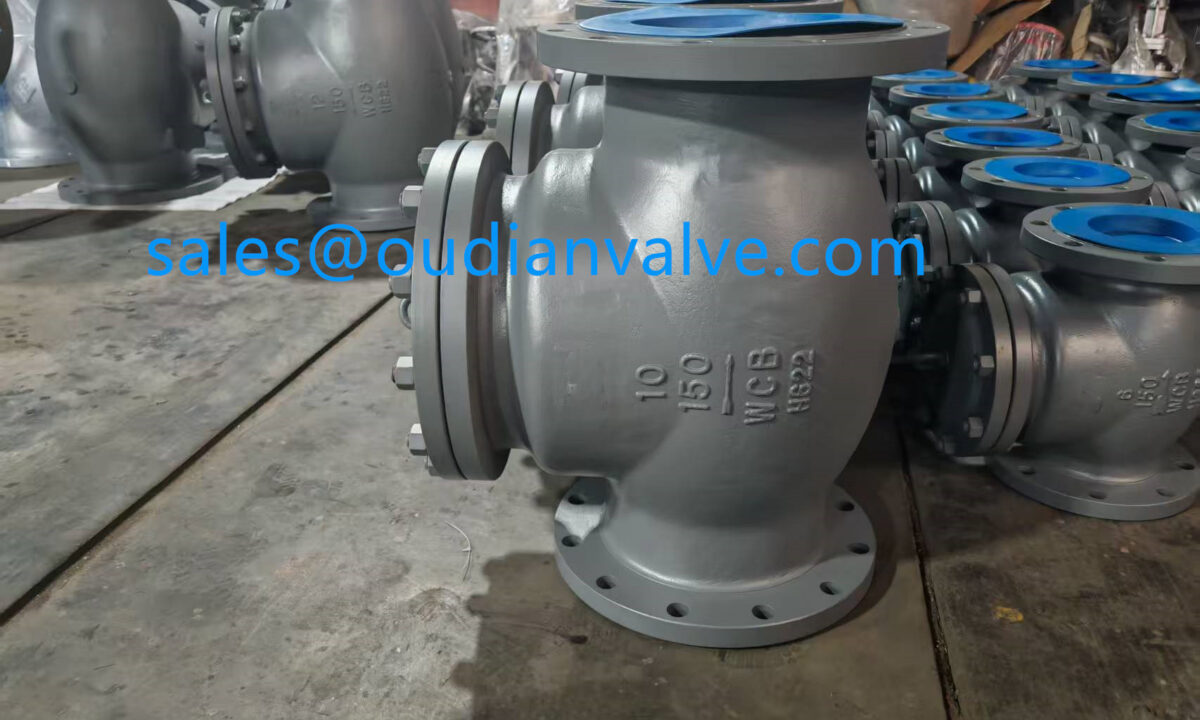
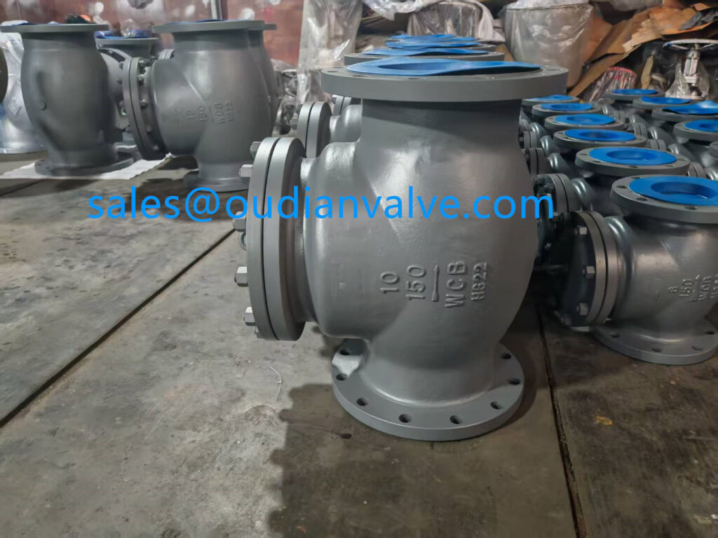
Swing check valves feature a hinged disc that arcs upward away from the valve seat under forward liquid momentum. Because the flapper swings largely out of the primary pathway in a properly sized installation, the open passage closely matches the cross-sectional area of the surrounding pipe. This unobstructed geometry makes swing models an efficient choice for low-friction gravity feeds and high-volume pump discharge lines where preserving static pressure is paramount.
Spring-loaded inline valves utilize a central disc or poppet guided along an axial stem, held closed by an internal coil spring until forward pressure overcomes the spring rating. While this design provides rapid shutoff and limits hydraulic transients, the disc and spring remain suspended directly in the center of the flow path. The liquid must divert around the obstruction, creating higher baseline friction and noticeable pressure drop compared to an open swing assembly.
Ball Check Valves
Ball check valves rely on a spherical ball that rises into an auxiliary chamber or moves linearly off an elastomeric seat during forward flow. Often used in wastewater and viscous pumping, the spherical shape creates substantial vortex shedding and pronounced pressure loss in clean water supply systems.
Dual Plate Wafer Valves
Dual plate valves incorporate two spring-loaded semicircular plates hinged across a central pin. This configuration offers rapid closing characteristics and balanced flow splitting, presenting moderate friction loss across medium and large diameter commercial mains.
Flow Rate Dynamics and Cracking Pressure
Cracking pressure represents the minimum upstream fluid force required to crack open the sealing mechanism and initiate measurable forward flow. Until the water pressure exceeds this mechanical threshold, the valve remains seated, blocking liquid movement entirely. Once this value is surpassed, additional pressure is consumed as the fluid works to push the closure element into its fully open, stable posture.
A frequent operational issue occurs when system flow rates remain too low to keep the internal component steadily open. If flow velocity fluctuates near the opening boundary, the disc or flapper hovers in a partially open position or repeatedly strikes the seat. This instability creates erratic pressure oscillations downstream, known as valve flutter, which introduces severe localized turbulence and accelerates component wear.
Achieving stable line pressure requires maintaining sufficient operational flow to force the internal mechanism against its travel stops. Fully retracted components minimize flow disruption, allowing dynamic water pressure to stabilize. System designs must therefore consider minimum anticipated consumption rather than sizing valves solely for theoretical maximum peak discharge.
Measuring inlet and outlet pressure confirms whether forward flow velocity is sufficient to achieve full valve opening.
Selecting an excessively stiff spring to ensure fast closure increases the required cracking pressure, which permanently robs downstream circuits of useful delivery head under low-flow scenarios.
Impact of Valve Sizing on Flow and Pressure
Selecting a check valve based solely on nominal pipe diameter frequently leads to improper sizing and undesirable pressure outcomes. When line designers match valve diameter to existing pipe runs without calculating actual flow rates, the valve often ends up oversized for the average velocity of the application. Oversizing produces insufficient velocity to lift and hold the disc open, causing pressure fluctuations and early mechanical degradation.
Conversely, undersized check valves act as severe bottlenecks that drastically increase fluid friction and reduce downstream pressure. Forcing high volumetric flow through an undersized valve bore accelerates the liquid to excessive speeds, transforming static head into dynamic velocity head and shedding substantial energy through fluid shear. This severe pressure drop limits fixture performance, increases pumping energy expenses, and can cause local cavitation around the seat.
Balanced valve sizing pairs internal passage volume with the actual volumetric demands of the facility. Ensuring that typical flow rates produce enough force to seat the disc fully open protects against premature wear while keeping unnecessary friction losses to an absolute minimum.
Oversized Valve Risks
- Inadequate fluid velocity allows the closure disc to flutter continuously.
- Unstable internal elements create irregular pressure surges downstream.
- Hinges, pins, and guide bushings experience accelerated mechanical fatigue.
- The valve disc may never reach its fully open position during normal demand.
Undersized Valve Risks
- Restricted internal bore creates an extreme, continuous pressure drop.
- High fluid velocities generate erosive wear on seats and internal walls.
- Downstream delivery falls short during periods of concurrent fixture use.
- Upstream booster pumps consume excessive electricity to overcome resistance.
Installation Orientation and Gravity Effects
The physical orientation of a check valve relative to gravity directly impacts the hydraulic force required to operate the closure mechanism. Swing check valves, for example, rely heavily on gravitational pull to assist the flapper in returning toward the seat when forward momentum ceases. Installing a swing check valve in a vertical line with upward flow requires the fluid to expend extra energy continuously lifting the heavy metal disc against gravity, increasing head loss.
Installing swing valves in vertical pipes with downward flow must be avoided completely. In downward flow orientations, gravity pulls the flapper away from the seat, preventing reliable closure and allowing significant backflow before any sealing occurs. Consequently, swing models are almost universally limited to horizontal runs or carefully evaluated vertical upward feeds.
Spring-assisted poppet and silent check valves function effectively in diverse physical orientations because their internal springs govern disc positioning rather than gravity. However, even spring-actuated units experience slight variations in required cracking force when fighting gravity in vertical risers. Placing valves in alignments that work harmoniously with their internal geometry avoids unnecessary pressure penalties and erratic closing behavior.

Correct mounting orientation ensures that internal flappers and poppets open completely without fighting unnecessary gravitational resistance.
Never mount swing check valves in vertical piping configurations with downward liquid flow, as gravity keeps the sealing flapper open and compromises reverse-flow protection.
Piping Layout and Upstream Turbulence
Fluid dynamics outside the valve body play a substantial role in maintaining steady system pressure and extending valve longevity. Liquid entering a check valve immediately after exiting an elbow, tee, reducer, or pump discharge exhibits swirling, highly turbulent velocity profiles. This non-uniform flow impinges on one side of the internal disc more than the other, causing erratic motion, incomplete opening, and amplified pressure loss.
To preserve laminar flow and minimize pressure drops, check valves require straight, unobstructed pipe runs both upstream and downstream. A straight run of pipe allows chaotic cross-currents to settle into a symmetrical velocity distribution before encountering the internal disc. This uniform velocity pushes evenly across the entire face of the closure mechanism, holding it firmly in the open position.
Downstream pipe configurations also require careful consideration to prevent backpressure fluctuations. Locating throttling valves or sudden pipe reductions immediately following a check valve creates backpressure waves that can destabilize the internal poppet. Designing a plumbing layout with adequate separation distances protects stable pressure profiles across the entire distribution network.
- Maintains a symmetrical fluid velocity profile across the face of the internal disc.
- Eliminates asymmetric side-loading on valve guide stems and hinge pins.
- Reduces secondary eddy currents that transform fluid pressure into wasted heat.
- Minimizes acoustic vibration and chatter that radiate into occupied building spaces.
Distinguishing Normal Head Loss from Mechanical Faults
Differentiating between the natural, designed pressure drop of a functional check valve and the severe losses caused by mechanical failure is essential for system maintenance. Every working valve exhibits a predictable differential pressure that stays proportional to the square of the flow velocity. When downstream pressure drops precipitously while upstream supply remains strong, the valve is likely suffering from an internal physical restriction rather than standard friction loss.
Auditory and tactile cues provide valuable diagnostic context when evaluating an installed valve. A healthy check valve operates almost silently during steady flow, with only a soft, singular click detectable when the mechanism seats as flow terminates. In contrast, chattering, clicking, or rattling during continuous flow indicates an unstable disc that is restricting passage and generating irregular pressure drops.
Installing differential pressure gauges upstream and downstream of critical valves allows operators to monitor performance trends continuously. A gradual rise in the pressure differential over months of operation points toward progressive mineral scale accumulation or debris binding the assembly. Sudden differential spikes usually reflect internal mechanical breakage, such as a sheared hinge pin or jammed guide stem.
Comparing inlet and outlet gauge values reveals whether pressure drop exceeds expected engineering tolerances.
| Operational Indicator | Normal Operation | Mechanical Malfunction |
| Acoustic Profile | Quiet | Continuous clicking, chattering, or loud metallic rattling. |
| Downstream-Druck | Stable | Sudden or extreme drops during standard fixture operation. |
| Differential Reading | Consistent | Progressive increases over time or sharp sudden spikes. |
| Flow Consistency | Smooth | Surging, pulsating, or severely choked volume delivery. |
Effects of Blocked, Damaged, or Stuck Valves
Mechanical degradation within a check valve introduces physical obstructions that choke fluid pathways and decimate downstream line pressure. When minerals precipitate out of hard water, scale forms thick, rough deposits along the internal body walls, guide pins, and seat rings. These mineral crusts increase surface friction and can physically bind the moving disc, preventing it from swinging or sliding into its fully open posture.
Foreign debris carried by municipal mains or well water supplies presents another common source of sudden pressure restriction. Sediment, sand grains, plumbing solder beads, and degrading pipe scale can become lodged between the valve disc and the body casting. Debris trapped in the flow passage reduces the net free area for water travel, transforming an ordinary valve into a severe hydraulic choke point.
Internal structural failures cause similar performance collapses. Springs inside poppet valves can suffer fatigue cracking or corrosion failure, leaving the disc loose and unable to align with flow lines. A dislodged or partially cocked disc creates immense downstream turbulence, cavitation zones, and an unacceptable reduction in usable pressure.
Mineral Encrustation
Hard calcium deposits coat the seat and guide surfaces, mechanically seizing the disc and preventing full travel during forward flow.
Particulate Lodging
Stones, pipe shavings, and sediment wedge inside internal clearances, choking the cross-sectional area and causing major pressure drops.
Mechanical Component Fatigue
Fractured internal springs and bent hinge pins cause the closure disc to tilt crookedly, blocking normal liquid progression.
Water Hammer Control and Dynamic Surge Pressure
Water hammer is a high-magnitude hydraulic shockwave generated when liquid momentum is abruptly halted or forced to change direction. When a distribution pump stops suddenly, water column momentum continues forward momentarily before reversing toward the supply source. If a slow-closing check valve permits this reverse flow to gain speed before slamming shut against its seat, an intense pressure surge radiates through the piping assembly.
These dynamic shockwaves can reach pressures many times higher than the standard working limits of the piping network. Uncontrolled pressure spikes can burst pipe joints, rupture expansion tanks, bend valve stems, and blow out delicate fixture seals. Managing these violent transients requires check valves engineered to close rapidly before reverse velocity develops.
Silent check valves equipped with responsive internal springs excel at mitigating dynamic surge pressures. The spring actively pushes the poppet toward the seat as forward liquid velocity decelerates, achieving complete closure an instant before true counterflow begins. By eliminating reverse flow slamming, spring-assisted valves stabilize system hydraulics, protecting equipment and dampening acoustic shock throughout the structure.

Spring-assisted silent check valves close smoothly before counterflow develops, safeguarding piping from pressure surges.
Fast-closing spring check valves prevent reverse fluid velocity from developing, stopping water hammer spikes that can rupture pipe fittings and damage mechanical equipment.
Inspection Steps and Diagnostic Procedures
Systematic diagnostic procedures help pinpoint whether weak water pressure stems from check valve degradation or broader supply issues. Before dismantling plumbing runs or ordering replacement parts, conducting non-invasive evaluations isolates the problem area and verifies internal conditions.
- Observe baseline static and dynamic pressures on upstream and downstream gauges while opening fixtures to identify abnormal differential drops.
- Use an acoustic listening probe or mechanic stethoscope on the valve body to check for rattling, chattering, or continuous scraping during water flow.
- Isolate the piping zone using local shutoff valves and relieve line pressure following standard safety procedures before opening any inspection ports.
- Remove the valve bonnet or access cover to inspect the internal disc, seating surfaces, and hinge mechanisms for mineral accumulation or wear.
- Check the physical mobility of the closure element by hand to confirm smooth, unhindered travel throughout its entire operational range.
- Flush the valve interior with clean water to clear out trapped sediment, mineral flakes, or construction debris before reassembling the bonnet.
When reassembling the valve, inspect elastomeric seals and bonnet gaskets for signs of hardening or mechanical pinching. Replacing worn internal springs and damaged seals during routine inspection cycles restores intended hydraulic performance and prevents unpredicted downstream pressure drops.
Practical Selection Criteria for Piping Assemblies
Specifying the right check valve involves balancing flow requirements, spatial limitations, and acceptable pressure drop parameters. Choosing a model that matches the chemical, thermal, and velocity conditions of the system ensures steady downstream delivery and long-term mechanical reliability.
Body material compatibility represents an essential consideration. Bronze and stainless steel provide excellent corrosion resistance in aggressive water conditions, minimizing internal roughness that drives up boundary friction over time. Cast iron bodies offer cost efficiency for large municipal or industrial lines but require resilient coatings to avoid heavy rust tuberculation that increases friction loss.
Seat design also influences pressure performance and sealing integrity. Resilient elastomeric seats form bubble-tight closures under low backpressure conditions but can degrade in high-temperature applications. Metal-to-metal seats tolerate severe temperatures and abrasive media, though they often demand higher backpressure to achieve a tight seal and may introduce marginally higher cracking resistance.
Matching body metallurgy and internal seat materials to local water chemistry prevents corrosion buildup that restricts forward flow.
Design Advantages
- Full-port swing valves minimize hydraulic resistance in high-volume circuits.
- Spring-assisted poppets prevent destructive water hammer in high-head pumping loops.
- Wafer styles fit into tight mechanical spaces between standard pipe flanges.
Design Limitations
- Spring-loaded poppets introduce higher baseline head loss than swing flappers.
- Swing check valves remain susceptible to slam when subjected to rapid flow reversal.
- Ball check assemblies require substantial physical space to accommodate the ball guide chamber.
When to Schedule Professional Plumbing Evaluation
While routine visual checks and simple debris clearing fall within standard maintenance routines, certain hydraulic issues demand specialized evaluation. Persistent, unexplained pressure loss across complex distribution loops often signals systemic imbalances that simple valve swaps cannot resolve. Licensed plumbing professionals and mechanical engineers possess the specialized diagnostic equipment required to measure transient surges and map hydraulic gradients accurately.
Complex installations, such as commercial booster pump skids, multi-zone hydronic heating systems, and municipal backflow prevention banks, involve strict regulatory standards. Tampering with certified backflow preventers or altering valve specifications in life-safety fire sprinkler risers can compromise building compliance and invalidate property insurance coverage.
A qualified professional can perform comprehensive flow capacity tests, calculate Reynolds numbers, and model system friction to determine whether line modifications or specialized valve styles are needed. Investing in professional diagnostics prevents recurring fixture starvation, protects valuable pumping machinery, and preserves balanced water pressure throughout the structure.
Certified backflow assemblies protecting drinking water connections require mandatory annual testing by licensed backflow technicians to verify mechanical integrity and proper pressure response.
Frequently Asked Questions
Do all check valves reduce downstream water pressure?
Yes, all check valves cause a slight reduction in downstream water pressure because energy is consumed pushing the internal mechanism open and overcoming boundary friction. In properly sized installations, this pressure loss is minor and does not noticeably impact normal fixture operation.
What causes a check valve to suddenly reduce water pressure drastically?
A sudden, severe drop in water pressure typically points to an internal blockage, such as trapped debris, a broken spring, or mineral scale holding the disc partially shut. When the internal mechanism cannot swing or slide open fully, it turns into a major flow restriction.
Which check valve type causes the least amount of pressure loss?
Full-port swing check valves typically produce the lowest pressure drop because the hinged flapper swings almost completely out of the central fluid path during forward flow. This design leaves an open, unrestricted passage that closely matches the surrounding pipe diameter.
Can an oversized check valve cause water pressure problems?
Yes, an oversized check valve can cause pressure instability because low fluid velocity is unable to hold the heavy disc fully open. This condition leads to disc fluttering, chattering noises, localized turbulence, and fluctuating downstream delivery pressure.
Does mounting a check valve vertically affect line pressure?
Mounting a check valve vertically can increase pressure loss if the fluid must continuously push the weight of the closure element upward against gravity. Furthermore, swing check valves should never be mounted in vertical lines with downward flow, as gravity prevents proper closure.
Summary of Check Valve Pressure Dynamics
Check valves introduce a minor, calculated pressure drop into piping systems while performing the vital role of preventing reverse flow and protecting equipment. Matching valve style, size, and orientation to actual flow velocities keeps friction losses minimal and avoids operational fluttering. Regular diagnostic checks, acoustic monitoring, and prompt removal of mineral scale ensure that check valves maintain steady downstream water pressure year after year.