


Gate Valve vs Stop Valve: Understanding the Differences
Deciding between these two valve designs requires evaluating process line pressure, allowable head loss, throttling demands, media cleanliness, and installation envelope constraints. Each mechanism exhibits specific mechanical strengths and operational limitations that determine long-term piping performance.
Mechanical Design and Operating Principles
Internal mechanical construction dictates how each valve regulates fluid movement through a pipeline. While both styles place a closing member across the flow path, the mechanical arrangement of the stem, seat, and closure member differs fundamentally between gate designs and stop mechanisms.
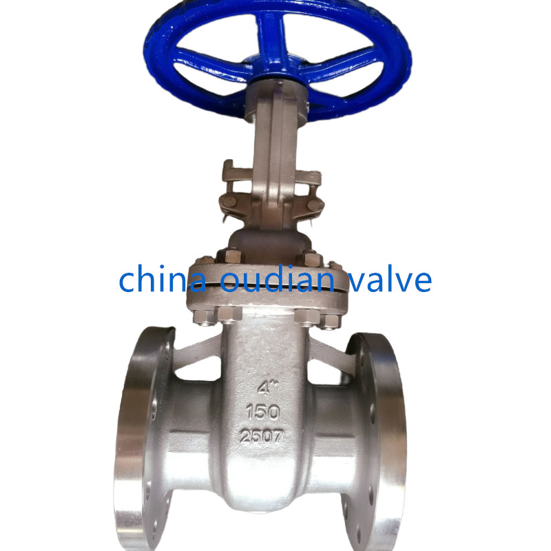
Gate valves use a gate or wedge that lowers completely across the diameter of the pipe bore. In the fully raised position, the gate retreats entirely into the valve bonnet, leaving a straight-through bore matching the internal pipe diameter. Actuation requires multiple full turns of a handwheel, drawing the threaded stem up or down depending on whether the unit employs an outside screw and yoke rising stem or an internal non-rising stem configuration.
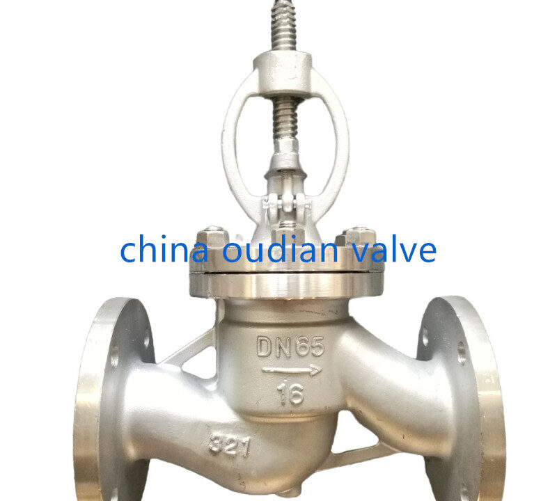
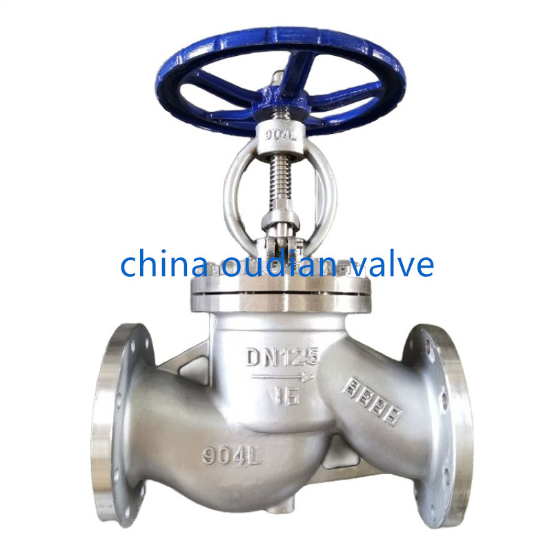
Stop valves incorporate an internal baffle or angled bridge wall that forces fluid through an internal orifice. A disc or plug mounted to the lower end of the stem moves toward or away from this horizontal seat to regulate or completely halt line passage. Rotating the handwheel shifts the disc relative to the seat opening, allowing fine adjustments to the annular space through which media travels.
Gate Valve Construction
Features a sliding wedge or parallel gate moving perpendicular to straight-through flow paths. The gate retracts into the bonnet to clear the line completely.
Stop Valve Geometry
Utilizes an internal seat partition where a movable plug or disc seals against an orifice. Media changes direction as it travels through the body chamber.
Stem Configurations
Rising stem designs provide immediate visual confirmation of gate position above the bonnet. Non-rising stems maintain a constant height profile to fit restricted installation spaces.
Flow Control Capabilities and Pressure Drop
Flow geometry through the valve body governs fluid velocity, turbulence, and system pressure retention. Selecting an improper internal pattern can generate severe line losses or induce structural cavitation.
A fully open gate valve produces negligible hydraulic resistance because the passage matches the interior profile of the connecting pipe. The straight flow path eliminates directional disruption, keeping pressure drop near zero in clear fluid systems. Throttling with a gate valve causes rapid flutter, seat erosion, and catastrophic vibration because high-velocity media strikes the partially exposed wedge bottom.
Stop valves inherently cause measurable head loss because incoming media must turn upward or downward to pass through the internal seat orifice before resuming its path. This internal detour generates turbulence and consumes hydraulic energy. However, this same geometry enables the plug or disc to manage intermediate positions without damaging chatter, giving operators predictable manual throttling across low and moderate pressure spans.

Gate valves must only operate in fully open or fully closed states to avoid vibration damage. Stop valves tolerate partial opening to adjust media volume, though they produce continuous line pressure drop even when fully open.
Sealing Performance and Installation Orientation
Sealing efficacy and pipeline mounting requirements depend on valve closure mechanics and intended flow direction. Mismatching valve geometry to line orientation invites persistent leakage and premature seat failure.
Standard wedge gate valves deliver bi-directional sealing, allowing installation without regard to upstream or downstream orientation. Fluid pressure pushes the upstream side of a flexible wedge firmly into the downstream body seat, forming a tight mechanical barrier. For optimal reliability, gate valves mount vertically with the stem pointing upward, preventing suspended debris from settling inside the bottom seat cavity where it could block complete gate travel.
Stop valves generally operate as uni-directional devices, featuring a stamped flow direction arrow on the cast body. Standard practice directs fluid beneath the disc seat, which assists manual valve opening and isolates the stem packing from line pressure while the valve rests in the closed position. Stop valves function smoothly in horizontal, vertical, or angled pipeline runs, making them practical for confined plumbing runs and equipment connections.

Verify flow direction markings before bolting stop valves into active lines. Gate valves support flow from either direction, but upright vertical orientation keeps sediment from wedging into the bottom seating pocket.
Direct Comparison Between Gate and Stop Valves
System designers must balance hydraulic efficiency against flow control flexibility when sizing process lines. Evaluating each mechanism across standardized engineering parameters clarifies the appropriate application boundaries.
Gate valves excel in bulk transmission pipelines where fluid moves continuously without regulation for extended intervals. Stop valves provide functional control in secondary branches, utility drops, and fixture run-outs where periodic adjustment or rapid shutoff takes priority over minimal line friction.
| Parametru | Supapă de poartă | Stop Valve | Engineering Implication |
| Flow Path | Straight-Through | Angled Orifice | Gate designs maintain full-bore passage while stop bodies redirect fluid internally. |
| Cădere de presiune | Minimal | Moderat | Gate valves preserve pumping head across long pipeline runs. |
| Controlul fluxului | On/Off Only | Throttling Capable | Stop valves accommodate flow modulation without destructive gate vibration. |
| Flow Direction | Bi-Directional | Uni-Directional | Stop valves require strict adherence to body flow arrows during installation. |
| Operation Speed | Multi-Turn Slow | Moderate Multi-Turn | Multi-turn operation protects high-pressure lines from dangerous water hammer surges. |
| Slurry Service | Specialized Knife | Unsuitable | Solid particulates clog stop valve seats and cause seat washing. |
| Pressure Range | High Pressure | Low-to-Moderate | Robust body wedges withstand intense industrial pipeline pressures. |
Maintenance Requirements and Operational Durability
Service longevity depends heavily on fluid composition, operational cycling frequency, and the mechanical accessibility of internal wear parts. Neglecting regular stem maintenance leads to stem binding or fugitive packing leaks over time.
Gate valves demand routine maintenance checks because high-pressure operation places heavy mechanical stress on the stem threads and bonnet packing. Stem lubrication prevents galling, particularly on rising stem models subjected to outdoor weathering or corrosive industrial atmospheres. If solid scale scores the internal body seats, repairing a standard wedge gate requires removing the valve body entirely from the line for machining.
Stop valves present lower maintenance overhead in routine service due to shorter internal stem stroke and less friction between the disc and the flat horizontal seat. When seat wear or disc degradation occurs, many stop valve patterns permit fast internal disc replacement simply by unbolting the bonnet assembly without removing the body casting from the piping. This repair convenience makes stop valves popular in utility networks where quick downtime recovery is vital.

Gate Valve Strengths
- Near-zero flow resistance in full-bore pipelines.
- Bi-directional sealing flexibility without reversal concerns.
- High mechanical pressure containment capacity.
Gate Valve Limitations
- Strictly unsuitable for flow throttling service.
- Requires greater vertical clearance for rising stems.
- Seat replacement demands complete valve unbolting.
Piping System Selection Guidelines
System designers select valve styles by matching pipeline performance criteria to valve geometry. Reviewing operating parameters before finalizing procurement prevents costly premature component replacements.
Evaluating media type, line volume, working pressure, and operational cycling guides the selection process through clear technical priorities:
- Define throttling needs: When the system requires manual volume regulation, install a stop valve to avoid gate vibration and seat scouring.
- Calculate pressure drop limits: For main supply headers where energy conservation is critical, choose full-bore gate valves to eliminate unnecessary friction.
- Assess media purity: In dirty fluids, pulp lines, or slurries, choose knife gate valves with sharpened edges rather than stop valves that trap solids around the seat.
- Measure installation clearance: Select non-rising stem gate valves or compact angle stop valves when ceiling heights or equipment frames restrict overhead clearance.
- Evaluate system operating pressure: Specify heavy-walled forged or cast steel gate valves for high-pressure industrial lines, reserving stop valves for low-to-moderate pressure branch circuits.
Frequently Asked Questions
Can gate valves be used for flow regulation?
No, gate valves are designed strictly for fully open or fully closed service. Operating a gate valve in a partially open position causes severe disc flutter, fluid turbulence, and rapid erosion of the internal sealing seats.
Which valve requires more maintenance, stop valve or gate valve?
Gate valves generally demand more routine maintenance due to their extended stem travel, external rising threads, and complex internal seating geometries. Stop valves feature simpler seat-and-disc arrangements that allow straightforward packing adjustments and quick disc replacements.
Are gate valves suitable for high-pressure applications?
Yes, gate valves are commonly deployed in high-pressure industrial pipelines and primary municipal water mains. Their heavy body castings, wedged disc geometry, and straight-through bore withstand severe hydraulic stresses effectively.
Do stop valves provide a visual indication of valve position?
Standard stop valves typically lack external position indicators, making it difficult to verify disc position at a glance. Conversely, rising stem gate valves clearly show whether the valve is open or closed based on how far the stem projects above the handwheel.
Can gate valves prevent leaks effectively compared to stop valves?
Gate valves provide tight shutoff in clean media lines, especially when equipped with precision metal wedges or resilient elastomeric seats. Stop valves seal reliably against their seats in low-pressure service, but high differential pressures can induce leakage across the seat disc over time.
What are the differences between wedge gate valves and parallel gate valves?
Wedge gate valves use an inclined, wedge-shaped closure member that wedges tightly between angled body seats to form a mechanical seal. Parallel gate valves employ flat, parallel seats and flat sliding discs, including knife gate designs that shear through slurries, viscous fluids, and suspended solids without binding.
Choosing the Right Valve Solution
Selecting between gate valves and stop valves requires aligning fluid mechanics with valve capabilities. Gate valves provide unobstructed, low-resistance flow for full on/off isolation in high-pressure mainlines, while stop valves offer dependable flow control and convenient maintenance for low-to-moderate pressure secondary systems. Evaluating line velocity, media purity, and throttling demands directs the correct valve choice for long-term piping integrity.