


Rising Stem Valves – Ball, Gate, vs. Non-Rising
Determining the appropriate valve requires matching system geometry, flow control needs, and physical installation clearances. While isolation services benefit from gate or ball configurations, precise fluid regulation relies on globe styles with specialized flow paths.
Working Principle and Mechanical Components
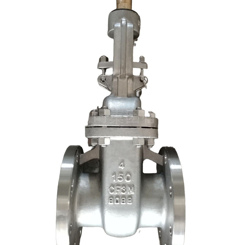
The operating mechanism of rising stem valves relies on external threading to translate rotational input into upward or downward thrust. Turning the handwheel or mechanical actuator turns a drive nut held securely within the valve bonnet. Because the nut remains fixed vertically while rotating, the threaded valve stem moves along a straight vertical path.
Placing the drive threads outside the valve body isolates mechanical components from line media. This exterior layout shields operating threads from erosion, scaling, and abrasive slurry accumulation. Technicians can visually determine the exact valve position from substantial distances by noting the exposed height of the shaft.
Because operating threads sit outside the fluid path, the stem threading requires periodic external greasing to prevent atmospheric corrosion and binding.
Linear travel requires durable packing seals where the smooth stem section penetrates the bonnet pressure boundary. Gland packing materials compress firmly against the traveling shaft to contain system pressures without restricting smooth vertical translation.
External stem threads remain outside the fluid chamber to support straightforward inspection and lubrication.
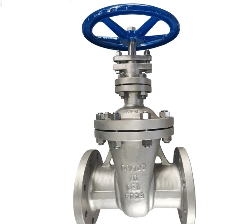
Rising Stem Gate Valves for Fluid Isolation
O rising stem gate valve functions strictly as an on-off isolation device rather than a throttling mechanism. Rotating the handwheel lifts the gate disc entirely out of the flow stream, creating an unobstructed passage with minimal pressure loss. When lowered to the closed position, the gate wedges tightly against parallel or angled body seats to halt liquid movement completely.
Industrial piping in high-pressure installations and large-diameter headers relies heavily on this design. Because the gate disc is either fully raised or fully seated, turbulence remains low during standard operation. Partial opening causes severe disc flutter, chattering, and seat erosion, making intermediate positioning inadvisable.
Avantaje
- Visual stem height provides immediate confirmation of open or closed status.
- Thread location outside the line prevents process scale buildup on drive surfaces.
- Unobstructed full-bore design lowers system pressure drop to negligible levels.
Limitări
- Requires substantial overhead vertical clearance during full stem extension.
- Unsuitable for throttling applications due to gate vibration and seat scouring.
- Exposed external threads face environmental dust, coastal salt, and atmospheric weather.
The clear valve position indication offered by the extended stem improves plant safety during line walkdowns. Personnel can confirm line isolation without relying on remote electronic telemetry or attempting to turn pressurized handwheels manually.
Rising stem gate valves deliver reliable shutoff across heavy utility and process fluid headers.
Rising Stem Globe Valves for Throttling Service
Unlike gate designs, a rising stem globe valve regulates fluid velocity and manages flow rates alongside tight isolation capabilities. Fluid entering the valve body changes direction to pass through an internal seat orifice positioned perpendicular to the pipe axis. The valve plug moves closer to or farther from this orifice, modulating flow area with predictable accuracy.
Piping standards typically recommend directing fluid underneath the disc so line pressure pushes upward against the closure member. Globe valve bodies incorporate a cast flow direction arrow to specify correct piping orientation. Because fluid assists opening or resists closure depending on inlet direction, actuator sizing calculations must account for flow direction forces.
T-Shape Body
The standard tee-pattern design positions the seat horizontal to the pipeline, offering high throttling precision across utility lines.
Y-Shape Body
The oblique body angles the stem and seat at an incline, straightening the fluid passage to lower flow resistance.
Angle Body
A ninety-degree configuration routes fluid through a right-angle turn, eliminating separate pipe elbows in compact layouts.
Because full upstream line pressure acts directly against the disc surface during closure, rising stem globe valves are typically limited to NPS 12. Larger sizes generate extreme thrust loads that make manual operation and compact actuation impractical. Shorter operating strokes allow rapid cycling compared to gate designs, supporting fast automation in cooling systems, fuel oil lines, and turbine drains.

Globe valve bodies feature cast direction arrows to establish correct flow orientation relative to the internal disc seat.
Rising Stem Ball Valves in Severe Environments
Rising stem ball valves unite the quarter-turn sealing efficiency of ball designs with the friction-free mechanical movement of linear stems. Unlike traditional floating or trunnion ball valves that scrape elastomeric seats during rotation, this specialized valve lifts the ball away from the seat before rotating. Stem guide grooves slide along a rigid guide pin to execute this compound mechanical motion.
This lifting motion eliminates mechanical friction between the spherical ball and the metal seating ring. Because the ball tilts away before turning, seat abrasion and seal rubbing drop to negligible levels. Lower operating friction reduces the torque required from mechanical actuators while extending component operational life.
All-metal construction allows rising stem ball valves to operate across extreme thermal conditions ranging from -200℃ up to 815℃.
During the closing stroke, fluid sweeps past the sealing surfaces at high velocity to flush away scale, particulates, and debris. Hardened ball surface coatings maintain seating integrity under severe media exposure, making the configuration dependable in critical petrochemical and refining processes.
The cam-action stem mechanism lifts the ball away from the seat to prevent seal scouring under severe service.
Rising Stem vs. Non-Rising Stem Valve Comparison
Selecting between rising and non-rising stem valves centers on physical space limitations, atmospheric conditions, and the need for immediate visual status verification. Non-rising stem gate valves maintain a constant overall height because the stem threads turn directly inside the gate disc within the body cavity. This compact profile makes non-rising configurations standard in underground utility vaults and tight marine machinery spaces.
However, enclosing the drive threads within the fluid stream exposes internal metal threading to line erosion, chemical attack, and suspended sediment. By contrast, rising stem designs isolate the threads above the bonnet, simplifying routine maintenance while providing unambiguous proof of open or closed status.
| Caracteristică | Rising Stem | Non-Rising Stem | Application Suitability |
| Position Proof | Direct Visual | Indicator Needed | Rising stems simplify status checks during facility walkdowns. |
| Space Demand | High Overhead | Compact Height | Non-rising stems suit tight vaults, trenches, and shipboard piping. |
| Thread Area | Outside Body | Inside Stream | Exposed threads avoid fluid corrosion but require external grease. |
| Întreţinere | Simple Access | Requires Teardown | Rising stem lubrication occurs externally without opening pressure boundaries. |
Where vertical clearance exists, rising stem gate valves remain favored across refining, chemical manufacturing, and power generation lines. Facilities prioritize external mechanical maintenance and positive position verification to maintain rigorous pipeline isolation procedures.
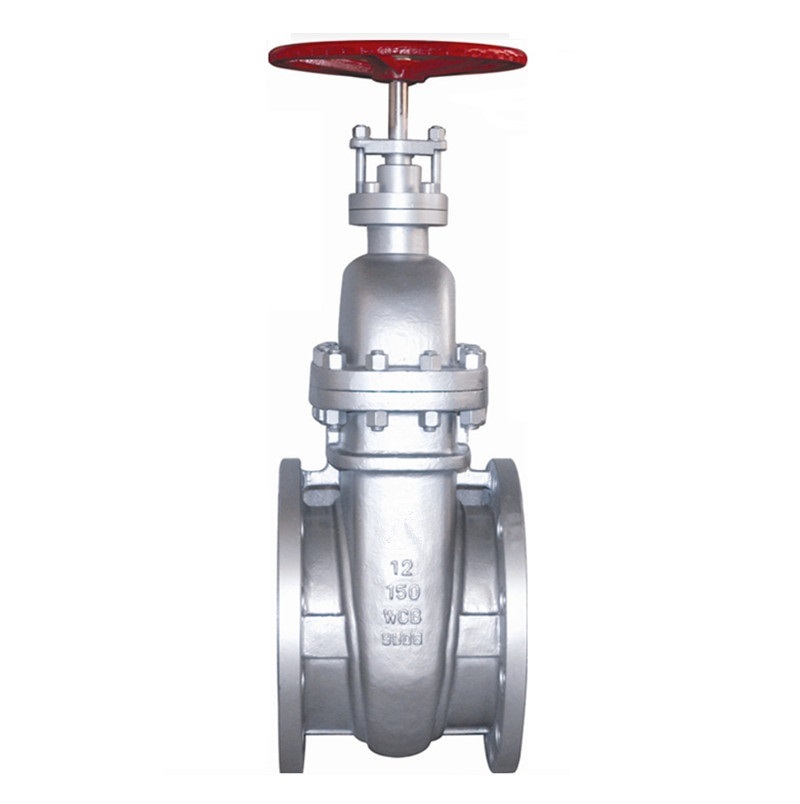
Overhead clearances must accommodate the full vertical extension of the stem during complete valve opening.
Selection, Maintenance, and Operating Safety
Safe operation of rising stem valves begins during the initial engineering design phase by verifying overhead envelope dimensions. Installers must confirm that surrounding cable trays, structural beams, and adjacent pipe runs do not obstruct full stem travel. Operating personnel require unobstructed access to turn handwheels and inspect packing glands safely.
Routine maintenance routines protect external mechanisms from premature wear and environmental fouling:
- Inspect the exposed spindle regularly for particulate accumulation, grit, and surface corrosion.
- Apply suitable lubricating grease to the exterior stem threads to maintain smooth travel through the yoke nut.
- Check the stuffing box gland bolts for balanced tightness to stop packing leaks without binding linear shaft movement.
- Verify stem thread protective tubes remain firmly in place over outdoor installations to shield grease from weather.
Personnel must never force a seized handwheel using auxiliary leverage bars, as excessive torque can twist the linear stem or shear yoke threads. When isolating high-temperature or high-pressure pipelines, operators should check stem height visually before confirming process lockout.
Frequently Asked Questions
How does a rising stem valve show position?
The valve stem lifts linearly as internal discs move off their seats, exposing the threaded shaft above the handwheel when open. When the valve is closed, the stem lowers completely, providing an immediate visual indication of disc position.
Why are rising stem globe valves limited to NPS 12?
Total line pressure acts directly against the entire globe disc area, transmitting high mechanical thrust into the stem assembly. Above NPS 12, manual operating torque and actuator requirements become excessively large for practical piping configurations.
What temperature range do rising stem ball valves tolerate?
All-metal rising stem ball valves operate reliably within thermal operating conditions ranging between -200℃ and 815℃. Their non-rubbing mechanical movement eliminates soft elastomeric seals that would otherwise fail under extreme process temperatures.
When should a non-rising stem valve be selected instead?
Non-rising stem valves are preferred in underground burial vaults, drainage channels, and tight mechanical spaces with limited overhead height. Because their stems rotate without extending upward, they fit into tight envelopes where rising stems would hit structural obstructions.
Selecting the Appropriate Valve Configuration
Rising stem valves offer dependable fluid isolation and throttling control across power generation, petrochemical, and general industrial piping. Matching the linear travel mechanism to available physical clearances protects equipment integrity while providing clear confirmation of flow conditions. Selecting the proper gate, globe, or ball design supports reliable fluid containment and long-term process safety.