


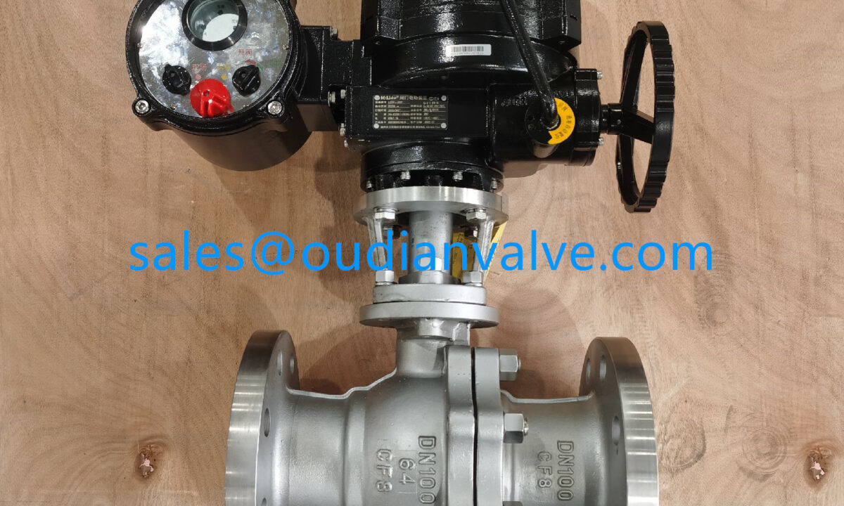
Pneumatic & Electric Ball Valve Comparison
Selecting between these automated platforms depends on facility utilities, required transit speed, control complexity, hazardous area classifications, and ongoing maintenance budgets. Reviewing each actuation technology against core operational demands clarifies which mechanical arrangement supports long-term process reliability.
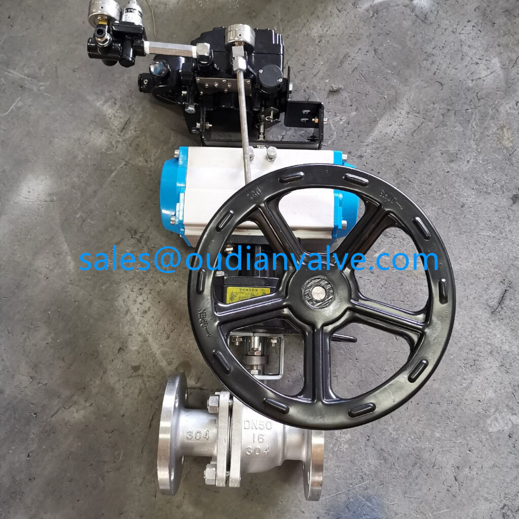
Operating Principles and Utility Infrastructure
Actuator mechanisms generate rotational force through fundamentally distinct physical energy conversions. Pneumatic ball valves convert pneumatic pressure into mechanical motion, whereas electric ball valves utilize an electric motor driving a gear reduction mechanism to pivot the valve stem.
Pneumatic systems typically utilize rack-and-pinion or scotch-yoke assemblies housed within an aluminum or stainless steel cylinder. Compressed air entering the ports forces pistons outward or inward, converting linear thrust into rotary motion that turns the ball through a quarter turn. This design generates immediate physical movement with minimal moving parts. When air exhausts, the mechanism depressurizes rapidly, keeping operational friction low inside the actuator barrel.
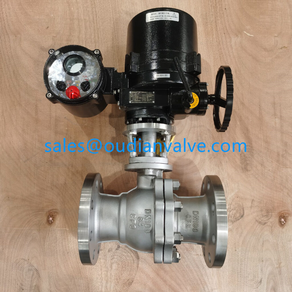
Electric actuators integrate an electric motor, multi-stage gear train, limit switches, and an electronic control board within a sealed enclosure. Electrical power drives the motor shaft, which steps down speed through spur, planetary, or worm gearing to amplify mechanical torque. The gear train remains mechanically locked or braked when power ceases, holding the ball securely against fluid flow dynamics.
Pneumatic Drive Requirements
Pneumatic setups require clean, dry compressed air routed through distribution headers, filter-regulator units, and directional solenoid valves. Mechanical exhaust creates distinct venting noise during cycling, which requires mufflers in enclosed work areas.
Electric Drive Requirements
Electric setups operate from alternating or direct current electrical feeds using standard industrial wiring conduits and terminal connections. Gear trains produce quiet, continuous motor humming during stroke travel without air discharge.
Installation complexity also differs between the two designs. Pneumatic units demand pneumatic piping, air preparation stations, and pilot solenoid wiring, creating a dual-utility requirement at the valve location. Electric units connect directly to existing power cables and signal lines, simplifying retrofits in facilities that lack dedicated compressor networks.
Actuation Speed, Torque Output, and Control Dynamics
Cycle times and mechanical output profiles dictate how each valve type responds to process demands. Pneumatic ball valves deliver rapid open-close cycles, while electric units provide controlled, deliberate valve travel suited for fine modulation.
Pneumatic actuators respond almost instantaneously to pilot air signals. Rapid piston travel drives the valve stem through a complete quarter turn in brief intervals, making pneumatic actuation preferred for emergency shutdown, rapid batching, and quick line isolation. Modulating flow with pneumatic units requires electro-pneumatic positioners, which regulate air pressure dynamically to hold intermediate ball positions against flow resistance.
Electric actuators operate at moderate stroke speeds governed by gear ratios and motor rotation limits. This deliberate transit prevents hydraulic shock and water hammer in liquid transport lines carrying dense fluids. Modern electric units incorporate digital microprocessors, optical encoders, and smart positioners that interpret analog or digital network signals directly, enabling precise valve positioning across continuous throttling processes.
Water hammer risk increases when high-velocity liquid lines close too quickly. While pneumatic actuators open and close quickly, electric units provide stable transit speeds that protect piping joints, gaskets, and flow meters from hydraulic surge pressures.
Torque delivery profiles also display notable variation across travel angles. Scotch-yoke pneumatic actuators generate peak torque at the start and end of each stroke, matching the natural breakout torque demand of ball valves as the ball seats and unseats. Electric actuators supply consistent torque across the entire travel path, backed by internal mechanical limiters and electronic torque sensors that stop motor operation if debris obstructs the ball cavity.

Reliability, Maintenance, and Environmental Suitability
Operating environments and mechanical wear patterns influence ongoing service requirements and plant uptime. Pneumatic and electric actuators demonstrate distinct durability profiles under extreme temperatures, repetitive cycling, and hazardous atmospheres.
Pneumatic actuators contain few internal components subject to friction or thermal stress. The pistons, springs, and O-ring seals tolerate millions of continuous operating cycles before requiring overhaul. Routine maintenance focuses on replacing soft elastomer seals, maintaining clean air filtration, and inspecting solenoid valve spools. The absence of electrical sparks makes standard pneumatic assemblies inherently safe in volatile atmospheres containing flammable vapors, combustible dust, or volatile gases.
Electric actuators house mechanical motors, bearings, capacitors, and microcircuits that require environmental protection. Repetitive cycling generates internal heat within the motor windings, imposing strict duty cycle limits to prevent thermal overload trips. Deployment in explosive or hazardous zones requires heavy explosion-proof enclosures certified to contain internal sparks or electrical faults, increasing assembly weight and physical footprint.
- Pneumatic assemblies withstand ambient temperature swings, humid washdown zones, and corrosive chemical environments with minimal sealing degradation.
- Electric actuators require internal anti-condensation space heaters to stop moisture buildup on delicate circuit boards during outdoor temperature drops.
- Fail-safe protection in pneumatic systems relies on internal mechanical coil springs that return the valve to a secure position if air pressure drops.
- Fail-safe protection in electric systems necessitates auxiliary battery backup modules, internal supercapacitors, or specialized mechanical spring-return gear modules.
- Continuous duty cycles cause minimal thermal buildup in pneumatic units, whereas high-frequency cycling in electric models can cause motor overheating.
Plant safety design often favors mechanical spring-return pneumatic actuators for critical isolation duty. If utility supplies drop, mechanical spring energy drives the valve closed or open without relying on stored electrical power, secondary wiring, or battery charge retention.

Advantages, Disadvantages, and Life-Cycle Costs
Assessing overall project viability involves balancing initial acquisition expenses against long-term maintenance and utility costs. Each drive system presents trade-offs that influence capital planning and facility operating expenses.
A bare pneumatic actuator presents lower initial procurement costs than an equivalent electric model. However, operating pneumatic equipment requires an ongoing supply of clean, dry compressed air. Generating compressed air involves continuous electrical power consumption by central compressors, desiccant dryers, line filters, and routine air distribution line leak repairs, which adds substantial indirect overhead over decades of plant operation.
Electric actuators carry higher initial equipment price tags due to internal electronics, precision gear machining, and motor components. Despite this upfront investment, electric units consume electrical power only during stem movement, drawing zero energy while holding a fixed open or closed state. When installed in locations lacking pneumatic piping, electric valves eliminate the substantial capital expenditure required to install new compressor headers and air treatment equipment.
Pneumatic Advantages
- Rapid transit speeds suit emergency isolation demands.
- Simple mechanical construction supports high cycle life.
- Inherently safe design operates reliably in hazardous zones.
- Mechanical spring return provides dependable fail-safe action.
Pneumatic Limitations
- Requires continuous access to clean, dry compressed air.
- Modulating position control requires extra electro-pneumatic hardware.
- Exhaust ports generate audible air discharge noise during cycles.
Weighing these attributes helps plant planners avoid utility overextension. When dozens of automated valves operate continuously in close proximity, central air compressors deliver economical pneumatic performance. Conversely, scattered or remote valves often prove more economical with standalone electric actuators.
Technical Comparison and Industrial Applications
Operational capabilities match specific processing conditions and piping architectures. Comparing core performance attributes side by side clarifies how mechanical characteristics translate to plant floor service.
| Performance Factor | Actionnement pneumatique | Actionnement électrique | Operational Significance |
| Actuation Speed | Rapid | Modéré | Pneumatic units cycle fast; electric units lower surge risk. |
| Utility Demand | Air comprimé | Electric power | Pneumatic requires air lines; electric needs local wiring. |
| Duty Cycle | Continuous | Rated limit | Electric motors generate heat under high cycling frequencies. |
| Fail-Safe Action | Mechanical springs | Battery or spring | Pneumatic springs provide self-contained mechanical return. |
| Hazardous Zones | Inherently safe | Certified housing | Electric actuators require explosion-proof ratings in vapor areas. |
| Position Control | External positioner | Integrated digital | Electric gear systems excel in stable intermediate throttling. |
| Operating Noise | Air exhaust | Quiet motor | Electric units operate silently without periodic air venting. |
Pneumatic ball valves are standard in chemical manufacturing, petroleum refining, power generation, and bulk materials handling. These environments demand spark-free actuation, rapid emergency shutdowns, and continuous duty cycles on primary process headers. Food and beverage washdown lines also favor stainless pneumatic actuators that resist aggressive caustic clean-in-place chemicals.
Electric ball valves serve extensively in commercial building automation, municipal water treatment, heating and cooling loops, and agricultural irrigation networks. Facilities managing wastewater pumping stations, boiler feed lines, and batch dosing skids value electric actuation for its standalone wiring and steady modulation accuracy without relying on auxiliary air compressors.
Selection Criteria for Automated Installations
Choosing the correct actuation method requires systematic evaluation of site conditions, process parameters, and operational goals. Following a structured assessment prevents misapplication and unsupported utility demands.
- Audit available site utilities to determine whether high-capacity compressed air lines already run near the piping location, or if only electrical conduits exist.
- Determine required transit speeds, verifying whether the line demands immediate isolation or controlled travel to reduce fluid momentum surges.
- Review valve cycle frequency, matching continuous high-repetition applications to pneumatic units and intermittent positioning to electric actuators.
- Assess process safety rules and fail-safe needs, confirming whether loss of main power requires immediate mechanical spring-assisted closure.
- Inspect environmental ratings, noting ambient temperature ranges, corrosive vapors, moisture washdown routines, and classified hazardous area requirements.
- Calculate total ownership costs, combining initial actuator purchase costs with the expenses of air infrastructure, electrical runs, and routine maintenance.
Applying these criteria early during piping design helps engineers balance rapid mechanical response against precision electronic automation. Aligning process requirements with the mechanical strengths of each drive system supports long valve service life and steady process control.
Frequently Asked Questions
How do fail-safe mechanisms differ between pneumatic and electric ball valves?
Pneumatic valves achieve fail-safe operation using internal mechanical springs that drive the valve stem open or closed if air pressure drops. Electric valves rely on auxiliary battery packs, internal supercapacitors, or complex mechanical spring-return gear modules to reposition the valve when power fails.
Which valve type operates faster during automated cycles?
Pneumatic ball valves operate substantially faster because air pressure moves pistons almost instantly across the cylinder chamber. Electric actuators cycle at controlled, moderate speeds determined by motor rpm and internal gear reduction ratios.
Can electric ball valves run continuously without overheating?
Electric actuators feature defined duty cycle ratings that prevent internal motor windings from overheating during frequent cycling. Pneumatic actuators tolerate continuous, repetitive cycling without heat buildup because expanding air dissipates thermal energy.
What utility maintenance is required for pneumatic actuators?
Pneumatic actuators require periodic replacement of dynamic O-rings, cleaning of air supply filters, and inspection of exhaust mufflers. Maintaining clean, dry, oil-free compressed air prevents internal corrosion and premature seal degradation.
Are electric actuators suitable for hazardous plant locations?
Electric actuators function safely in hazardous environments when equipped with certified explosion-proof enclosures that isolate internal sparks. Pneumatic actuators are inherently non-sparking, making them simpler to install across classified vapor and dust zones.
Summary of Valve Actuation Choices
Balancing pneumatic and electric ball valves centers on aligning utility availability, response timing, duty cycles, and fail-safe safety requirements. While pneumatic drives provide rapid cycling, high endurance, and inherent safety in harsh atmospheres, electric actuators deliver quiet, self-contained positioning accuracy wherever electrical power is accessible. Evaluating system constraints against these mechanical characteristics ensures dependable fluid control and sustainable operating costs.