

Types of Check Valves and Their Industrial Applications
Selecting the proper valve configuration depends on the physical state of the media, line pressure, flow variability, and installation orientation. Matching the specific closure mechanism to operational variables helps avoid operational hazards such as severe water hammer, excessive pressure loss, and premature mechanical wear.
Fundamentals of Reverse Flow Prevention in Industrial Piping
Check valves serve as automatic non-return barriers in fluid-handling systems. Fluid movement through the upstream port pushes the closure element away from the seat, allowing fluid to travel downstream. When fluid velocity decreases or direction reverses, gravity, spring force, or backpressure forces the closure element back onto the seat, closing the passageway.
The minimal upstream pressure needed to initiate flow and unseat the internal mechanism is known as the cracking pressure. Springs of varying stiffness can be incorporated to adjust cracking pressure according to system requirements. A steady differential pressure across the valve keeps the closure element fully open and stable during routine operations.
Without functional non-return devices, process reversal can cause catastrophic damage to rotating machinery. Centrifugal pumps and compressors are particularly vulnerable to reverse rotation when shutdown occurs. Backflow can also contaminate treated water supplies, drain storage vessels unexpectedly, and create damaging pressure surges.
Proper valve sizing must be based on minimum and continuous flow rates rather than nominal line pipe size to prevent internal fluttering and premature mechanical failure.
Swing Check Valves: Design and Operation
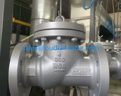
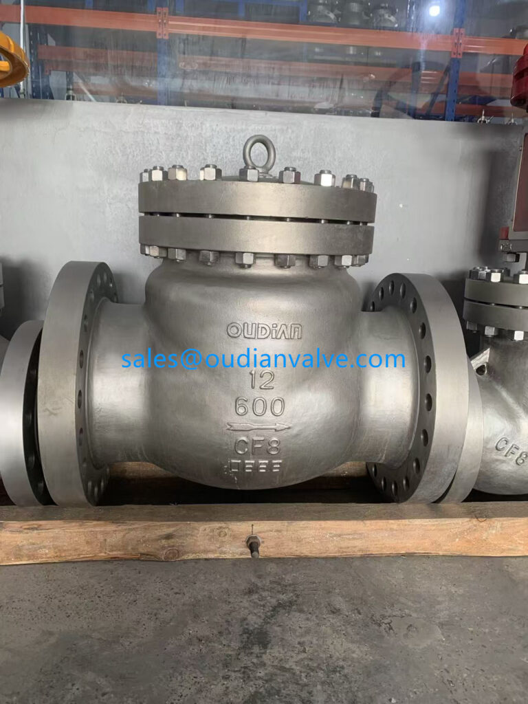
A swing check valve utilizes a movable disc suspended from an overhead hinge pin or trunnion. Forward fluid flow pushes against the disc surface, swinging it upward into an open position away from the fluid pathway. When forward velocity drops, the disc swings back downward under gravitational pull and seats firmly against the stationary sealing ring.
Because the disc swings almost entirely clear of the fluid stream in the fully open state, swing check valves exhibit very low resistance to fluid movement. This low pressure drop makes the design practical for systems where continuous pumping efficiency and low operating head losses are critical. The full-port interior also allows the passage of mechanical pipeline pigs during inspection procedures.
The free-swinging design can, however, be susceptible to slamming when rapid flow reversal occurs. In systems with reciprocating pumps or fluctuating discharge pressures, the disc may slam violently against the seat, producing pressure spikes known as water hammer. Swing units are primarily suited for horizontal piping runs, though vertical installations with upward flow are acceptable under steady operating conditions.
Vorteile
- Low pressure drop due to an unobstructed flow path.
- Accommodates pigging operations in liquid pipelines.
- Simple mechanical construction with few moving parts.
Einschränkungen
- High susceptibility to slamming during fast flow reversals.
- Requires substantial travel distance to achieve full closure.
- Limited suitability for vertical downward flow lines.
Lift and Piston Check Valves for High-Pressure Services
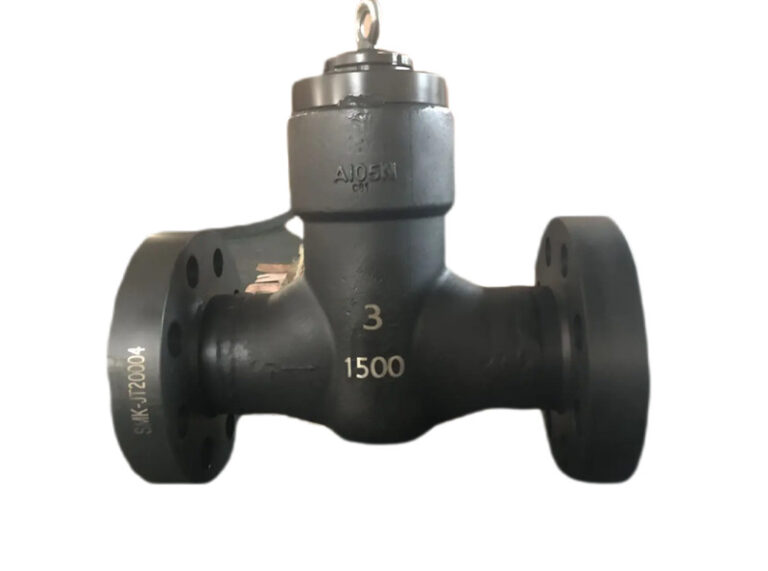
Lift check valves operate via a guided disc that moves vertically perpendicular to the fluid flow path. Upstream pressure forces the disc upward off its horizontal seat, directing the fluid through an internal globe-style flow chamber. When line pressure drops below cracking thresholds, gravity or an internal spring forces the guided stem back onto the seat.
Piston check valves represent a heavy-duty variation of the lift design, incorporating a precision-machined piston that travels within an internal dashpot cylinder. As fluid pulses occur, the dampening cylinder acts as a hydraulic cushion, restricting sudden movements of the piston. This hydraulic dampening action stabilizes the closure element during turbulent or pulsating flows, minimizing valve chatter.
These configurations are widely deployed in high-pressure steam lines, boiler feed networks, and gas compression loops. The internal globe body design introduces higher head loss compared to swing mechanisms, but the shorter travel stroke of the piston enables rapid response times. The compact stroke length significantly reduces mechanical shock during unexpected system shutdowns.
- Internal dampening cylinders cushion mechanical impact during flow surges.
- Short linear travel distance delivers rapid closure against fast reversals.
- Precision stem guides maintain consistent alignment under high differential pressures.
- Body design restricts practical use to clean gases, steam, and filtered liquids.
Ball Check Valves for Viscous Media and Slurries
A ball check valve uses a spherical closure member that lifts off an internal circular seat when forward line pressure overcomes the weight of the ball. In many designs, an internal chamber guides the ball away from the central flow channel, maintaining a clear passage for the process fluid. As flow ceases, backpressure and gravity direct the spherical element back onto the seat to prevent reverse flow.
The rotating nature of the ball ensures that the sealing surface wears evenly over its operational lifetime. As the ball tumbles during opening and closing cycles, fluid movement sweeps contaminants off the sealing perimeter. This self-cleaning characteristic prevents solids accumulation and makes ball check valves effective for wastewater, heavy slurries, and viscous media.
Because the ball must move into an offset recess or lift against fluid flow, these valves introduce moderate pressure drops across the pipeline. Units can be equipped with metallic balls, rubber-coated cores, or synthetic elastomer spheres to match fluid abrasiveness and chemical reactivity. Horizontal orientations and vertical lines with upward fluid flow represent the standard configurations for these assemblies.
Vorteile
- Spherical rotation promotes uniform surface wear and longevity.
- Resists clogging in viscous fluids, slurries, and suspended solids.
- Available with diverse elastomeric coatings for tight shutoff.
Einschränkungen
- Higher pressure drop compared to full-port swing designs.
- Requires adequate fluid velocity to keep the ball stable in the chamber.
- Not suitable for vertical lines carrying downward fluid flow.
Wafer and Dual-Plate Check Valves for Compact Spaces
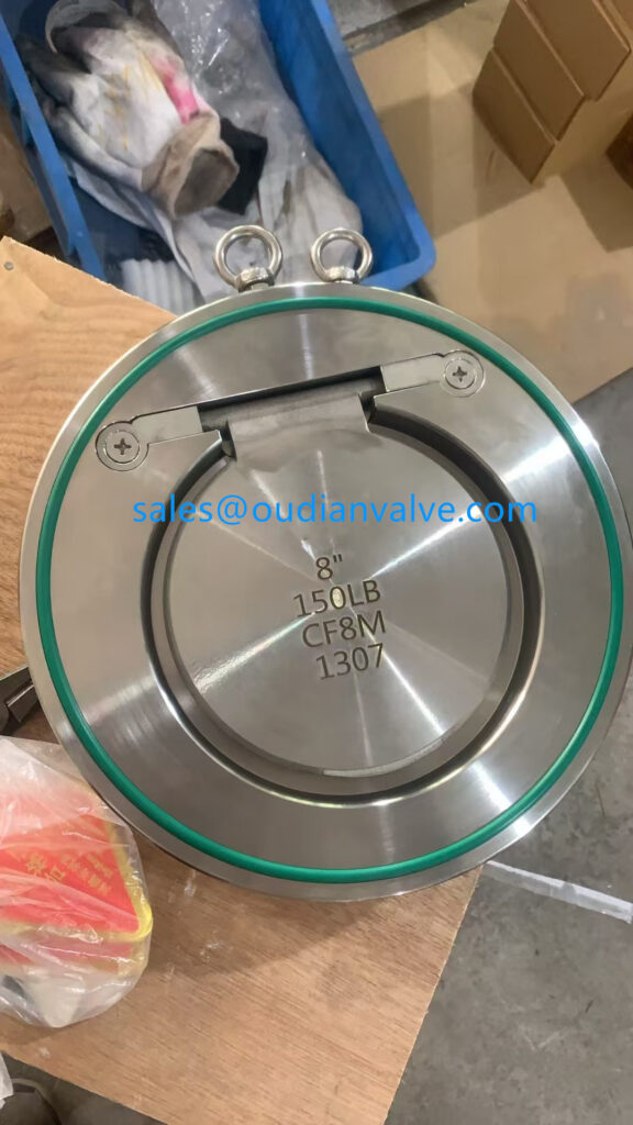
Wafer check valves are engineered with narrow, flangeless bodies designed to clamp directly between two standard pipe flanges. Dual-plate check valves, also referred to as split-disc or butterfly check valves, feature two semicircular plates mounted on a central hinge pin. When forward flow commences, the two plates fold together like wings, allowing fluid to travel downstream along both sides of the central pin.
Torsion springs mounted on the hinge pin actively push both plates toward their closed position as fluid velocity slows down. Because the plates begin closing before reverse flow actually accelerates, dual-plate designs significantly lower the risk of water hammer. The lightweight plates travel only a short distance, enabling dynamic closure characteristics across fast-reversing liquid piping.
The compact footprint of the wafer body reduces installation weight, structural support requirements, and mechanical stress on surrounding pipe flanges. These attributes make wafer and dual-plate check valves practical for offshore platforms, municipal pumping stations, and large-diameter cooling loops where space and structural load limits are critical.
Compact Wafer Profile
The short face-to-face dimensions simplify retrofitting into crowded piping corridors. Reduced structural mass lowers overall pipeline support requirements across large nominal diameters.
Spring-Assisted Fast Response
Independent torsion springs force the dual plates shut prior to complete flow reversal. This pre-emptive closing dynamic dramatically reduces hydraulic shock in municipal and industrial networks.
Diaphragm and Silent Check Valves for Pulsation Control
Diaphragm check valves rely on a flexible rubber or synthetic elastomeric membrane that deflects under upstream pressure to permit fluid movement. When differential pressure drops, the inherent elasticity of the diaphragm forces it back against an internal support plate or body partition. Because there are no rigid sliding metal stems, diaphragm valves respond rapidly to minute pressure changes and operate cleanly with corrosive liquids.
Silent check valves, also known as nozzle check valves or center-guided spring check valves, utilize an aerodynamically contoured disc mounted on a central guide stem. A heavy coil spring continuously biases the disc toward the seat. Forward flow pushes the disc straight back against the spring, and as soon as forward velocity decelerates, the spring drives the disc shut before fluid direction reverses.
By closing at zero flow velocity, silent check valves prevent backflow slam and suppress pressure shock waves across drinking water, building mechanical systems, and condensate networks. The continuous spring tension and guided disc travel allow these units to be installed in any orientation, including vertical downflow pipelines, provided the flow matches the internal design parameters.
Inspect elastomeric diaphragms regularly for chemical embrittlement, hardening, or fatigue caused by continuous pressure cycling or elevated operational temperatures.
Operating Comparison of Types of Check Valves
Selecting among check valve types requires evaluating physical valve properties against hydraulic pipeline conditions. Each design offers specific trade-offs regarding response time, flow resistance, orientation flexibility, and mechanical resilience. The operational parameters below provide a direct structural comparison across standard industrial valve formats.
| Valve Design | Druckabfall | Closing Speed | Solids Handling | Flow Orientation | Water Hammer Risk |
| Swing | Sehr niedrig | Mäßig | Fair | Horizontal mostly | Higher risk during rapid flow reversal |
| Piston Lift | Hoch | Fast | Arm | Horizontal only | Low risk due to hydraulic dashpot action |
| Ball | Mäßig | Mäßig | Exzellent | Horizontal or vertical | Moderate risk depending on line velocity |
| Dual-Plate | Niedrig | Fast | Fair | Any orientation | Low risk due to spring assistance |
| Silent Nozzle | Mäßig | Very Fast | Arm | Any orientation | Minimal risk due to closure at zero velocity |
| Diaphragm | Mäßig | Fast | Gut | Any orientation | Low risk due to flexible membrane action |
Pressure drop variations reflect the geometry of the internal flow path. Full-port designs like swing valves minimize pumping energy costs, whereas guided-disc and globe-style lift valves introduce localized head losses that must be factored into continuous system head calculations.
Check Valve Performance Across Major Industrial Sectors
Fluid processing environments place distinct mechanical demands on check valves based on fluid chemistry, pressure cycles, and cleanliness standards. Valve bodies, internal trim, and seating materials must be matched to operational media to prevent unexpected mechanical failure. Different industrial sectors rely on specific configurations to maintain safe daily operations.
Öl und Gas
High pressures and sour crude require forged steel swing, piston, or dual-plate valves with corrosion-resistant trim to prevent backflow into production manifolds.
Chemische Verarbeitung
Corrosive acids and volatile solvents demand lined ball or diaphragm check valves made from fluoropolymers and specialty nickel alloys to withstand harsh media.
Wasser und Abwasser
Municipal water works favor non-slam silent check valves to stop water hammer, while raw sewage lift stations rely on non-clogging ball check valves.
Power generation facilities utilize heavy-duty lift and piston check valves on high-pressure boiler feed pump discharge headers and extraction steam lines. The dynamic stability provided by internal dashpots protects turbines from backward steam induction during trip events. In HVAC hydronic loops, silent check valves prevent water hammer noise and mechanical shock across multi-story building riser networks.
Hygienic sectors such as pharmaceutical manufacturing and food processing demand sanitary diaphragm or spring-assisted disc check valves constructed from polished stainless steel. Crevice-free internal surfaces and compliant elastomeric seals support thorough cleaning-in-place and steam-in-place procedures without disassembling process lines.
Technical Evaluation Criteria for Valve Specification
Selecting the right check valve involves balancing multiple hydrodynamic, physical, and spatial factors. Overlooking dynamic operating variables can lead to noisy valve chatter, seat erosion, or catastrophic pressure transients. Engineers and plant operators should systematically review operating parameters before standardizing valve models.
- Characterize the fluid state, viscosity, chemical aggressiveness, and the presence of entrained solids or fibrous materials.
- Establish the maximum, normal, and minimum continuous flow rates to ensure sufficient dynamic pressure exists to hold the valve open.
- Identify system pressure and temperature boundaries to determine appropriate valve body ratings and compatible seating materials.
- Assess pipeline orientation, noting whether flow moves horizontally, vertically upward, or vertically downward.
- Evaluate system vulnerability to water hammer to decide whether spring-assisted or silent non-slam designs are needed.
- Confirm available face-to-face installation space and structural weight limits to choose between flanged bodies and wafer styles.
Sizing must never rely solely on matching nominal pipe diameter. Installing an oversized check valve causes the closure member to hover partially open during low-flow periods, resulting in rapid hinge pin wear, seat fretting, and operational chatter. Matching the valve to actual flow velocity maintains the internal element in a stable, fully open position.
Preventive Inspection and Maintenance Protocols
Check valves operate automatically without external indication, making routine inspection essential for identifying internal wear before backflow occurs. Common mechanical issues include disc chatter, seat leakage, broken internal springs, and hinge pin galling. Developing a proactive inspection schedule based on operational severity supports long-term equipment reliability.
Periodic acoustic monitoring and ultrasonic leak detection can reveal internal seat leakage while the valve remains in service under reverse pressure. Significant temperature differentials across a closed valve can also signal backflow leakage of hot or cold process fluids. During scheduled turnarounds, disassembling flanged bodies allows direct visual inspection of internal elastomeric seats, metallic seating faces, and closure springs.
When replacing internal components, match trim metallurgy and elastomer formulations directly to original equipment specifications. Replacing weakened springs restores appropriate cracking and closing dynamics, reducing the likelihood of valve slam. If disc chatter occurs persistently in a running system, evaluate whether downstream flow turbulence from nearby elbows or throttled control valves is disrupting internal mechanics.
Locate check valves at least five to ten pipe diameters downstream from pumps, elbows, or pipe reducers to minimize turbulent flow conditions that induce disc flutter.
Frequently Asked Questions
What causes check valve slamming in liquid systems?
Check valve slamming occurs when a slow-closing disc remains open during flow deceleration and is slammed shut by high-velocity reverse flow. This sudden deceleration generates high pressure shock waves known as water hammer.
Can check valves be installed in vertical downward flow lines?
Most standard check valves cannot operate in vertical downflow lines because gravity counteracts the closing mechanism. Only specific spring-assisted silent or nozzle check valves with springs sized to overcome disc weight are suitable for downward flow.
How does cracking pressure affect system operations?
Cracking pressure determines the upstream differential pressure required to initially unseat the closure element and establish flow. A cracking pressure that is too high increases pump head requirements, while one that is too low can result in improper valve seating.
What are the operational differences between soft seats and metal seats?
Soft seats utilize elastomeric or thermoplastic materials to deliver bubble-tight shutoff in clean, low-temperature services. Metal seats provide mechanical resilience against high temperatures, steam erosion, and abrasive slurries, though slight leakage may occur under low differential pressures.
Why is line velocity critical when sizing a check valve?
Line velocity must generate sufficient dynamic lift force to hold the internal closure member fully open against its stops. Low velocity causes the closure element to float and chatter, which damages hinge pins, springs, and sealing faces.
Summary of Check Valve Selection Priorities
Selecting the appropriate check valve design requires an accurate assessment of fluid media, operating velocity, system pressures, and potential water hammer risks. By aligning closure mechanics, body configurations, and seat materials with the exact demands of the industrial process, engineers maintain steady single-direction flow, protect upstream equipment from mechanical shocks, and extend the operating life of fluid-handling infrastructure.