

Valve Symbols: A Complete Guide to Reading P&ID, Hydraulic, and Pneumatic Diagrams

Fundamental Elements of Valve Symbols
Every valve symbol consists of modular graphic elements that assemble to define the physical body, flow path, connection ports, and operating mechanism of the component. Recognizing these geometric primitives allows quick decoding of complex valves even when viewing an unfamiliar diagram format.
In standard process prints such as a piping instrumentation diagram, the core valve body appears as two facing triangles meeting at their apexes. This bowtie shape represents the fluid boundary and piping interface. Fluid power diagrams instead use square envelopes to illustrate internal valve chambers and switching positions.
Actuator attachments mount directly to the valve body shape, revealing the driving force that shifts the internal mechanism. Adding small lines, diagonal slashes, or secondary geometric enclosures establishes how energy enters the device to alter flow conditions.
- Body Envelopes: Facing triangles designate inline process valves, while conjoined squares signify internal shifting spools in pneumatic and hydraulic machinery.
- Flow Path Lines: Internal solid lines show open conduit routes, while perpendicular hash marks or terminated tees depict completely blocked passages.
- Actuator Stems: Centerlines rising from the body connect to circles, diaphragms, cylinders, or manual handles that dictate valve positioning.
- Return Springs: Zigzag lines denote mechanical springs that exert continuous force to restore a valve to its unactuated resting state.
- Solenoid Coils: A small rectangle containing a single diagonal slash identifies an electrical solenoid actuator that converts power into linear mechanical movement.

Symbols for Isolation and Throttling Valves
Isolation and throttling hardware represents the majority of inline process components across plant piping systems. Standard drawings use subtle modifications to the basic bowtie shape to indicate whether an internal element slides, rotates, or plugs into the seat.
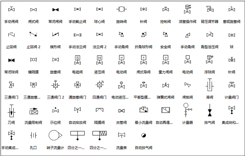
A gate valve symbol shows two plain opposing triangles, designating a linear-motion wedge that moves perpendicular to process fluid flow. Globe valves insert a solid or open center circle between the triangles, representing a plug that throttles flow through a contoured orifice. Ball valve symbol drafting places an open circle in the middle of the triangles or uses distinct diagonal line treatments across the body to denote rotary quarter-turn shutoff.
Butterfly valve symbols feature an inclined line or thin bar cutting through the center of the valve shape, illustrating a disc rotating on an internal shaft. Needle valves adapt the globe symbol by incorporating an explicit arrow point aimed into the center, marking fine manual flow control capability.
| Ventiltyp | Motion Type | Symbol Marker | Primary Function |
| Gate | Linear | Plain triangles | Positive isolation without pressure loss |
| Globe | Linear | Center circle | Throttling flow and precise regulation |
| Ball | Rotary | Circle between triangles | Quick quarter-turn isolation service |
| Butterfly | Rotary | Centerline bar | Compact throttling and line isolation |
| Needle | Linear | Tapered point arrow | Micro-metering and instrument protection |
Distinguishing between these symbols helps maintenance personnel understand pressure drop characteristics across a line. Throttling designs create distinct turbulence profiles, whereas full-port isolation hardware preserves line velocity without restriction.
Symbols for Non-Return and Pressure Relief Valves
Automatic line valves respond directly to system fluid dynamics rather than external mechanical operators or electrical commands. Schematics use asymmetric internal geometry to convey automatic responses to backpressure and overpressure occurrences.
A check valve symbol features an internal flap, angled plate, or floating ball resting against a seat inside the bowtie envelope. The check valve design permits forward motion while blocking countercurrent flow through mechanical interference. Directional check valves often include an arrow or angled slash that highlights the permitted process stream orientation.
Pressure relief valves and safety valves protect pipe integrity and pressure vessels against structural damage. These symbols combine an angled outlet path with a spring or weight indicator pushing downward against line pressure. When process force overcomes the mechanical spring rating, the graphic pathway shows flow dumping toward an exhaust line or disposal header.
Relief safety valves draw an angled outlet perpendicular to the inlet conduit, with an external sensing pilot line or integral spring box. The discharge arrow always points away from the protected pressure envelope toward safe recovery systems.
Pressure-reducing valves share structural similarities with relief devices but monitor downstream conditions rather than upstream surges. Their schematic lines connect downstream pilot signals back to the actuator bonnet to modulate flow orifice openings automatically.
Solenoid and Directional Control Valve Symbols
Fluid power schematics describe directional control valves by grouping multiple square envelopes into a continuous assembly. Each distinct square shows an internal operational state, with arrows illustrating port-to-port connections and blocked tees representing closed routes.
Technicians define directional valves by their port count and switching position total. A three-port, two-position design appears as two contiguous squares with three external connection points, commonly abbreviated as a 3/2-way valve. The square adjacent to an active actuator reflects the flow path currently conducting fluid power.
Actuation symbols attach to the outer edges of the combined valve boxes. Mechanical push buttons, hand levers, foot pedals, hydraulic pilot lines, pneumatic pilot lines, and electrical solenoids all possess unique graphic markers.
P&ID Actuation Symbols
- Circle mounted atop an extended stem depicts an instrument control loop.
- Diaphragm dome indicates air-operated modulation with pressure balancing.
- Electric motor box contains letter designations such as M or MOV.
- Handwheel displays a horizontal crossbar or T-handle over the stem.
Fluid Power Operators
- Diagonal line in a box indicates an electromagnetic solenoid coil.
- Small triangle exterior to the box indicates internal pilot pressure feed.
- Parallel angled lines indicate manual foot pedal or treadle mechanics.
- Zigzag line shows a mechanical spring return mechanism on the opposite side.
When electric power energizes a solenoid, the internal spool shifts across the graphic plane. Reading the box furthest from the spring return reveals the actuated state, whereas the box aligned with the spring depicts resting geometry.
Differences Across P&ID, Hydraulic, and Pneumatic Schematics
Drawing conventions differ depending on whether the graphic represents chemical refining, hydraulic force distribution, or pneumatic machine automation. Engineering organizations standardize these drawings using distinct guidelines to maintain consistency within specific industries.
The International Society of Automation maintains ISA 5.1, which directs drafting rules for piping instrumentation diagrams. P&ID prints highlight equipment connectivity, instrument tags, and piping classes rather than physical component interiors. Valves appear as inline symbols connected to instrument bubbles that define communication protocols.
The International Organization for Standardization establishes ISO 1219, which governs hydraulic and pneumatic fluid power graphics. These symbols detail internal mechanical logic, flow passage volume, and energy conversion paths rather than piping size or physical installation geometry.
| Drawing Standard | Primary Focus | Valve Representation | Actuator Documentation |
| ISA 5.1 | Process piping | Bowtie shapes | Instrument loop bubbles |
| ISO 1219 | Fluid power logic | Enclosed squares | External mechanical symbols |
| DIN / EN | European systems | Modified bowties | Integrated hardware tags |
Recognizing the active governing standard prevents misinterpreting process prints. A circle placed above a valve denotes a control system sensor on a P&ID, whereas an identical circle on a fluid power drawing represents a manual mechanical roller operator.
Identifying Normal Positions and Actuator Markings
Schematics illustrate fluid systems in their quiescent, unpowered, and de-energized condition to provide a consistent baseline. Understanding valve symbols requires knowing how to interpret resting positions, fail-safe modes, and flow arrows.
In process piping, letters adjacent to a control valve define fail-safe operation upon air or power loss. The letters FC indicate Fail Closed (normally closed), FO represents Fail Open (normally open), and FL marks Fail Locked, which retains the last physical position. Directional arrows positioned on the actuator stem also point upward for fail-open and downward for fail-closed configurations.
Solid fill patterns inside valve symbols frequently distinguish operating states. On process drawings, a fully blackened bowtie or darkened sector often designates a normally closed valve, while an open outline designates a normally open valve.
Drawing legends take absolute priority over general habits. Certain facilities utilize filled shapes to mark normally closed valves, while others use fill patterns exclusively to identify specific packing or seat materials.
Fluid power schematics indicate the unactuated state by examining which square envelope connects directly to the exterior supply and working lines. In a two-position valve with spring return, line connections attach directly to the resting envelope in the drawing.

Avoiding Common Schematic Interpretation Mistakes
Misreading engineering drawings can lead to incorrect manual valve line-ups, faulty maintenance teardowns, or dangerous fluid handling situations. Adhering to structured review practices minimizes operational mistakes during plant operations.
A frequent error involves confusing check valves with reduction fittings or flow nozzles due to overlapping triangle elements. Check valves always exhibit an internal barrier, hinge point, or directional dart, whereas pipe reducers show solid boundaries without internal flow-checking elements.
Another common mistake is misinterpreting three-way valves on process drawings. Reviewers must confirm whether a three-way valve serves as a diverting valve that splits one stream into two, or a mixing valve that unites two streams into a common outlet.
- Always Verify Drawing Legends: Review the project cover sheet to confirm whether darkened symbols denote normally closed valves or distinct metallurgy.
- Follow Pilot Line Connections: Distinguish dashed pilot pressure lines from solid process conduits to avoid mistaking auxiliary actuation lines for main supply headers.
- Check Upstream Flow Arrows: Trace flow lines backward to equipment sources to verify whether an inline check valve allows forward processing or blocks backflow.
- Confirm Revision Blocks: Verify drawing release stamps before beginning field servicing, as valve models and actuator arrangements frequently change during upgrades.
Frequently Asked Questions About Valve Symbols
What is the basic symbol for a manual valve?
A manual valve appears as two opposing triangles meeting at a central point, forming a bowtie shape. A central stem line extends outward from the intersection, topped with a flat horizontal line or T-bar that denotes a manual handwheel or lever.
How does a ball valve symbol differ from a globe valve symbol?
A ball valve symbol displays an open circle inside or across the meeting point of the two triangles. A globe valve symbol places a solid filled circle or a distinctly bordered plug directly between the triangles to represent an orifice obstruction.
What do the letters FO and FC mean next to a valve symbol?
The abbreviation FO indicates Fail Open, meaning the valve moves to the open position if actuation power or air supply drops. The abbreviation FC indicates Fail Closed, meaning internal springs push the valve shut during a power interruption.
Why do hydraulic valve symbols use multiple squares?
Hydraulic symbols use connected squares to represent distinct mechanical spool positions. Each individual square shows the exact internal flow routing and port closures that occur when that specific position shifts into alignment with the external piping.
Summary of Valve Symbol Identification
Interpreting valve symbols accurately requires identifying the basic body envelope, examining internal flow lines, and noting attached actuator indicators. Verifying local drawing legends and standard conventions supports reliable schematic analysis across process, hydraulic, and pneumatic systems.