

Different Types of Valves Used in Piping
Valve procurement can account for 20 to 30% of total piping construction budgets, and unit costs vary significantly between different mechanical architectures. Selecting an optimal design requires matching functional requirements with fluid properties, operating pressures, temperatures, and long-term piping layout constraints.
Primary Functions of Valves in Piping Systems
Piping systems rely on valves to execute discrete mechanical functions based on process conditions. Matching the correct internal construction to the required task avoids mechanical damage, seat erosion, and process disruptions.
Isolation valves act as basic on-off barriers to allow complete shutoff during equipment maintenance or emergency shutdowns. When fully open, these components provide an unobstructed passage to reduce line friction and conserve pumping energy across extended pipeline lengths.
Regulation valves modulate pressure and flow rates by deliberately creating managed pressure drops through restricted flow paths. Non-return valves prevent fluid reversal to protect pumps and sensitive measuring instrumentation from water hammer and backflow surges.
Overpressure protection represents a distinct safety function handled by spring-loaded or pilot-operated relief valves. These devices discharge surplus mass when system pressure exceeds set limits, preserving downstream pipe walls and pressure vessels.
Directional control valves, including multiport three-way and four-way models, divert or combine flow streams from converging pipe branches. Combining multiple flow paths into a single valve reduces the number of welded joints, flanges, and physical fittings required in congested plant racks.
Gate Valves: Linear Motion Isolation and Solid Shutoff
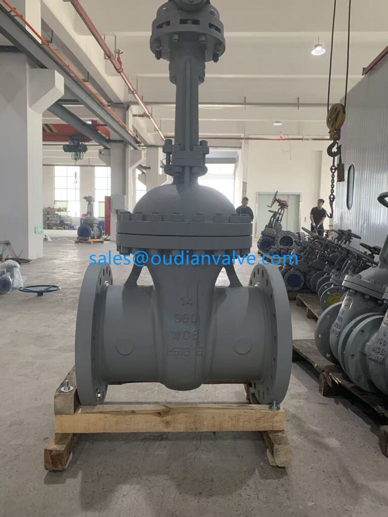
A gate valve is a linear motion device that inserts a flat or wedge-shaped disc directly across the fluid path to start or halt fluid flow. Because the disc retracts entirely into the valve bonnet when fully open, gate valves create negligible pressure drop and resistance across the piping system.
These components are intended solely for fully open or fully closed service. Using a gate valve in a partially open position causes fluid velocity to vibrate the unsupported wedge, leading to chattering, seat scoring, and premature seal failure.
Wedge designs vary according to system demands. Solid wedges provide high mechanical strength in low-vibration utility lines, flexible wedges accommodate thermal expansion and pipe strain without binding, and split-wedge parallel disc assemblies allow tight double-sealing in high-pressure steam and gas lines.
Преимущества
- Negligible pressure drop and minimal flow restriction when fully open
- Bi-directional sealing capability across wide operational pressure ranges
- Broad compatibility with hydrocarbons, steam, air, feedwater, and slurry media
Ограничения
- Unsuitable for throttling applications due to disc vibration and erosion
- Slow manual operation requiring multiple full rotations of the handwheel
- Prone to thermal binding and seat galling under fluctuating process temperatures
Stem configurations divide gate valves into outside screw and yoke designs and non-rising stem designs. Outside screw and yoke models expose the stem threads above the packing gland, keeping them free of corrosive process fluids while providing a clear visual indication of disc position. Non-rising stem models retain the threaded stem inside the body, making them suitable for underground utility mains and shipboard piping with restricted vertical clearance.
Rising stem gate valves offer clear visual verification of open and closed status during pipeline operations.
Globe Valves: Flow Regulation and Precision Throttling
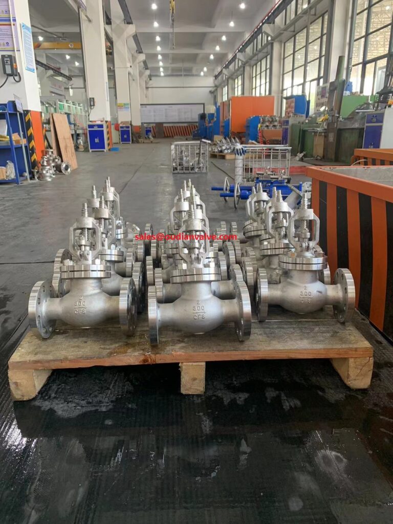
A globe valve uses a linear-moving disc that seats against an internal annular opening perpendicular to the pipe centerline. This internal path forces process fluid to change direction twice, creating controlled flow resistance suitable for precise flow throttling.
The proportional relationship between disc position and flow orifice area makes globe valves reliable for manual and automated flow control. Seating contact occurs evenly around the circumference, facilitating leak-tight shutoff even under persistent throttling conditions.
Globe valves are categorized into three body configurations based on port alignment and pressure drop characteristics:
- Z-body configurations feature a horizontal seat partition that produces high turbulence and substantial head loss, making them standard for basic water and steam service.
- Y-body configurations orient the seat and stem at an acute angle to the pipeline axis, providing a straighter flow path with significantly reduced pressure drop.
- Angle-body configurations place inlet and outlet connections at a ninety-degree angle, serving as both a directional pipe elbow and an accurate flow regulator.
Because line pressure acts directly against the underside or topside of the disc, operating torque requirements are higher than those of gate valves. Larger sizes typically require gear operators or balanced plug designs to overcome static fluid thrust during actuation.
Globe valve bodies create controlled internal turbulence to facilitate predictable flow regulation across varied pressure ranges.
Check Valves: Automatic Backflow Prevention
Check valves operate automatically without external manual control or actuators, relying entirely on pipeline fluid pressure and backpressure to open and close. When forward flow exceeds cracking pressure, the closure element lifts or swings open; reversal of flow seats the element to prevent backflow.
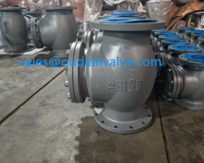
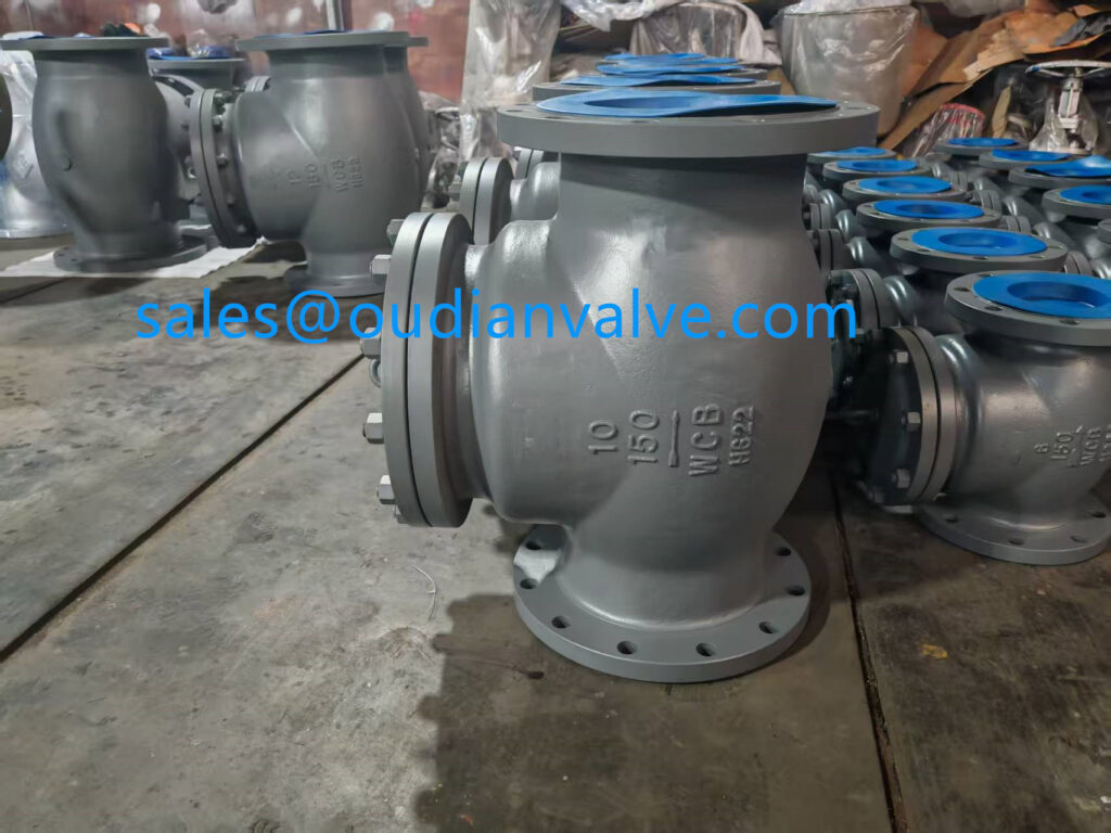
Swing check valves feature a hinged disc that pivots on a top-mounted hinge pin, swinging clear of the line under full forward flow. These units perform well in horizontal piping carrying low-velocity fluids or liquids with suspended particles, though rapid flow reversal can cause sudden disc slamming.
Lift check valves employ a guided piston or ball that rises vertically from its seat when forward fluid pressure pushes upward. These designs provide swift closure under backpressure, making them common in high-pressure gas, air, and steam services with high-frequency cycling.
Dual-plate wafer check valves use two spring-loaded semicircular plates mounted on a central hinge pin. The spring assistance initiates closure before forward flow completely stops, substantially reducing hydraulic shock and water hammer in pumping installations.
Stop-check valves combine the automatic backflow protection of a lift check with the positive shutoff mechanism of a globe valve. An independent threaded stem can be driven down to hold the disc closed against the seat, allowing the valve to function as an isolation barrier during boiler shutdowns.
Wafer style check valves conserve space between pipe flanges while delivering responsive backflow protection.
Ball Valves: Fast Quarter-Turn Isolation
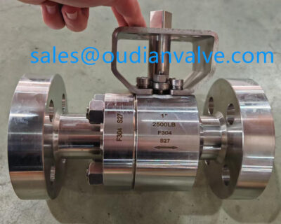
A ball valve is a quarter-turn rotary valve that uses a spherical disc with a drilled cylindrical bore to regulate or halt fluid flow. Turning the valve handle ninety degrees aligns the bore with the pipe axis to open the valve or turns it perpendicular to block fluid passage.
The rotary mechanism enables fast operation, making ball valves well suited for emergency isolation duties. Smooth internal bore geometries in full-port models provide minimal flow resistance, allowing pipeline pigging tools to traverse the valve without obstruction.
Industrial piping employs two primary ball mounting configurations to handle internal fluid forces:
Floating Ball Design
- Ball is suspended between two resilient polymer seats
- Upstream pressure pushes the ball downstream into the seat for sealing
- Operating torque increases rapidly at elevated working pressures
- Common in small-bore and lower-pressure industrial process piping
Trunnion-Mounted Design
- Ball is anchored by top and bottom mechanical trunnion shafts
- Floating seat rings are driven against the ball by springs and line pressure
- Operating torque remains stable and manageable under extreme pressure
- Standard for large-diameter pipelines, transmission grids, and high-pressure duties
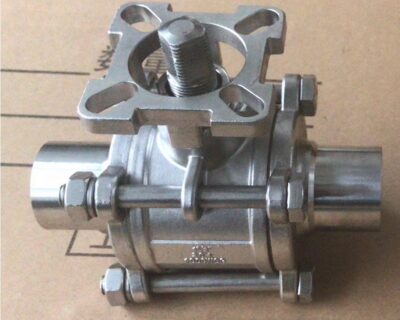
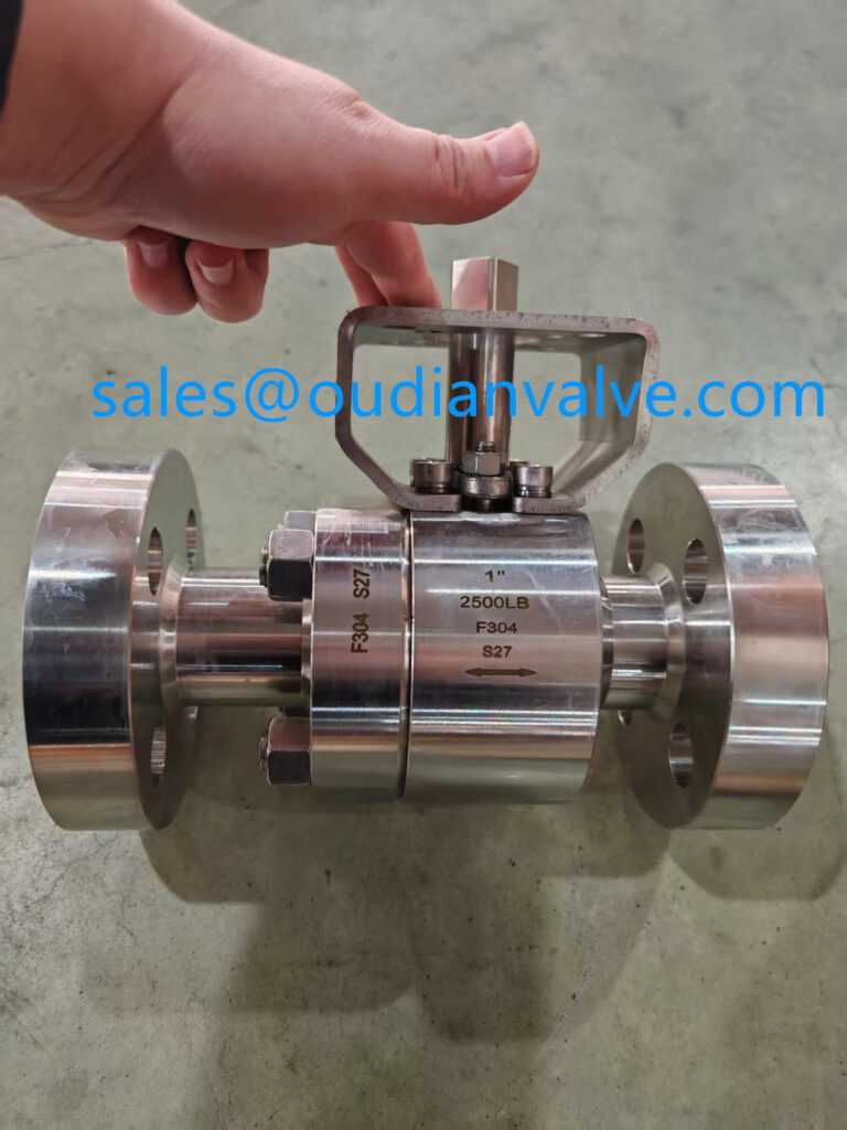
Body construction styles include one-piece welded bodies, two-piece split designs, and three-piece bolted bodies. Three-piece valves allow operators to unbolt the central body section for seat and seal servicing while retaining the end connections securely on the pipeline.
Ball valves deliver bubble-tight isolation with a simple quarter-turn motion, reducing actuation cycle times.
Plug Valves: Cylindrical and Tapered Rotary Shutoff
A plug valve is a rotary motion valve utilizing a cylindrical or conical plug containing one or more hollow passages through its body. Rotating the plug ninety degrees positions the passage in line with the pipe ends for flow or turns the solid metal body across the flow path for positive shutoff.
Plug valves provide bubble-tight shutoff in compact mechanical envelopes, making them common in upstream oil and gas production, high-pressure refining, and vacuum applications. Their wiping action across the seat surface prevents the accumulation of sticky deposits, scale, and suspended solids.
Port geometries influence flow characteristics and pressure drop across the installation. Round-port designs match the internal cross-section of the adjoining pipe, diamond-port variations provide improved throttling modulation, and standard rectangular ports offer reliable on-off isolation at lower manufacturing expense.
Lubricated plug valves require periodic grease injection through the stem to maintain an elastic seal film and prevent metal-to-metal plug seizure. In installations where maintenance access is difficult, non-lubricated models with fluoropolymer body sleeves reduce galling risks without external lubrication.
Multiport configurations introduce three or four fluid connections within a single plug valve casing. A single plug rotation can divert fluid from one vessel to another, bypass heat exchangers, or blend multiple input streams without complex manifold piping.

Plug valves handle abrasive process slurries and high operating pressures through robust rotary wiping action.
Butterfly Valves: Compact Control for Large Diameters
A butterfly valve controls fluid flow using a flat circular disc mounted on a central rotating shaft inside a short, narrow body. Rotating the shaft ninety degrees places the disc parallel to the stream for maximum flow or perpendicular to the stream against an internal seat ring for tight shutoff.
Due to their narrow face-to-face dimensions and reduced weight, butterfly valves provide cost savings in large-diameter piping systems compared to bulkier gate or globe valves. They serve both on-off isolation and throttling duties in cooling water circuits, chemical distribution, and low-pressure gas mains.
Disc offset geometries dictate sealing performance and service limits across varying process temperatures and pressures:
Concentric (Zero Offset)
The shaft is centered along both the valve body and disc plane. An elastomer seat lines the body, providing resilient bubble-tight shutoff in low-pressure utility, municipal water, and heating services.
Double Offset (High Performance)
The shaft axis is offset from both the disc seal center and the valve centerline. The cam-like disc path lifts smoothly off the seat during opening, reducing seal friction and extending operational packing life.
Triple Offset (Metal Seated)
Adds an angled conical seat contact axis to the double-offset geometry. The disc contacts the metal seat only at final mechanical closure, allowing frictionless operation in extreme-temperature hydrocarbons and steam.
End connections for butterfly valves include wafer patterns that slide between adjacent pipe flanges, lug configurations with tapped threaded holes for dead-end service, and flanged bodies for heavy structural duty. Wafer designs minimize installation weight, while lug designs permit downstream pipe removal while holding upstream line pressure.
Triple offset butterfly valves deliver metal-to-metal shutoff under elevated temperatures and pressures without disc scuffing.
Needle, Pinch, and Diaphragm Specialty Valves
Specialty valves address specialized operating demands such as micro-metering, abrasive slurry transport, and ultra-pure fluid isolation. These valves employ distinctive mechanical geometries that safeguard fluid purity or protect mechanical parts from corrosive process media.
Needle valves feature an elongated, finely threaded stem terminating in a sharp conical point that mates with an equally tapered seat. The small orifice and multiple handwheel turns enable micro-metering of fluids, making them indispensable on instrument takeoffs, pressure gauge snubbers, and analytical sampling lines.
Pinch valves utilize a flexible elastomeric sleeve clamped by a mechanical pinch mechanism to adjust or close the flow path. Because fluid contacts only the internal rubber sleeve, pinch valves handle aggressive chemical slurries, mining tailings, and pneumatically conveyed powders without clogging internal moving parts.
Pinch Valve Operational Limits
Pinch sleeves rely on flexible elastomers, restricting operating limits to moderate pressures and temperatures. Sleeve wear occurs through mechanical flex fatigue and abrasive wear, requiring planned sleeve inspections during outages.
Diaphragm Valve Cleanability
Diaphragm valves isolate process fluid from the stem and bonnet using an impermeable membrane. This design eliminates packing gland leakage risks, making it widely utilized in sanitary pharmaceutical and corrosive acid lines.
Weir-type diaphragm valves incorporate an internal saddle that elevates the seat, reducing the mechanical stroke required to achieve bubble-tight shutoff. Straight-through diaphragm valves present a completely unobstructed bottom bore, allowing viscous sludge and abrasive fluids to pass with minimal friction.
Diaphragm valves segregate internal bonnet mechanisms from corrosive or sterile fluids, preventing external stem leakage.
Pressure Relief and Safety Valves for Overpressure Protection
Pressure relief valves and safety valves protect process equipment, piping systems, and storage tanks from excessive internal pressures or structural collapse under vacuum conditions. These self-actuated devices open automatically at a predetermined set pressure to vent excess fluid mass and reclose once standard pressures return.
Safety valves are characterized by rapid pop-action opening driven by an internal huddling chamber, making them suitable for compressible gases, air, and steam. Direct spring-loaded relief valves open proportionally to rising line pressure, providing smooth thermal overpressure protection on non-compressible liquid lines.
Pilot-operated relief valves utilize line pressure acting on a larger internal piston to hold the main valve seated tightly until the small pilot sensing valve triggers. This arrangement allows operational pressures to run close to set pressure without seat weeping or seat simmer.
Vacuum relief valves and pressure-vacuum safety valves protect thin-walled atmospheric storage tanks from buckling inward during rapid pump-out cycles or thermal cooling. Calibrated weights or light springs lift internal discs to admit ambient air when internal vapor space pressure drops below ambient levels.
Non-reclosing pressure relief devices, such as bursting rupture discs, provide instant pressure discharge in applications where polymerizing or highly viscous fluids could foul mechanical spring seats. Rupture discs are frequently mounted upstream of conventional relief valves to act as an impermeable barrier against corrosive fumes.

Pressure safety valves provide autonomous overpressure release to safeguard pressure vessels and structural pipe runs.
Valve Motion and Actuation Classifications
Piping valves are categorized mechanically by the kinematic motion of the closure member and by the actuation method used to reposition the stem. Understanding these mechanical categories aids engineers in sizing actuators, calculating operating cycle speeds, and configuring pipeline control loops.
Closure mechanisms operate via linear motion, rotary motion, or quarter-turn rotary displacement. Linear valves use a stem that translates linearly into or out of the body, providing high positional precision at the expense of slower operational cycles.
Rotary valves swing or pivot an internal element about an axis, while quarter-turn valves represent a rotary subtype requiring a ninety-degree rotation to travel from fully open to fully closed. This quick operation allows rapid system isolation, although fast closure on liquid systems increases water hammer risks.
| Тип клапана | Motion Category | Primary Function | Typical Actuation Method |
| Gate | Linear | Isolation | Manual handwheel or electric motor multi-turn actuator |
| Globe | Linear | Throttling | Pneumatic diaphragm or linear electric actuator |
| Мяч | Quarter Turn | Isolation | Manual hand lever or quarter-turn pneumatic actuator |
| Butterfly | Quarter Turn | Dual Duty | Worm gear operator or pneumatic rotary piston |
| Plug | Quarter Turn | Isolation | Manual wrench or double-acting pneumatic cylinder |
| Check | Self Actuated | Non Return | Internal fluid dynamic pressure and spring return |
| Diaphragm | Linear | Dual Duty | Manual handwheel or spring-return pneumatic actuator |
| Relief | Self Actuated | Избыточное давление | Калиброванная винтовая пружина или внутренний пилотный механизм |
Выбор привода зависит от требуемого крутящего момента, частоты срабатывания, наличия сжатого воздуха или электропитания, а также требований к отказоустойчивости. Автоматизированные пневматические приводы обеспечивают надежное позиционирование в открытом или закрытом положении с пружинным возвратом при потере подачи сжатого воздуха, в то время как электроприводы обеспечивают точное многооборотное позиционирование на запорных клапанах большого диаметра.
Key Selection Considerations for Piping Systems
Выбор подходящего клапана требует оценки параметров процесса, структурных напряжений в трубопроводе и доступа для технического обслуживания, а также бюджета на капитальное оборудование. Разработчики систем должны одновременно учитывать множество эксплуатационных факторов, чтобы предотвратить преждевременный выход компонентов из строя и утечки вредных веществ.
Типы концевых соединений определяют эффективность монтажа трубопроводов, потенциальную вероятность утечек и простоту демонтажа клапанов при капитальном ремонте. Фланцевые соединения остаются стандартом на нефтегазовых и нефтехимических предприятиях, резьбовые соединения используются для приборов малого диаметра (менее двух дюймов), соединения, приваренные встык, предотвращают утечки в условиях сильной вибрации и малого диаметра трубопроводов, а соединения, приваренные встык, предназначены для работы в паропроводах высокого давления и высокой температуры.
Конструкторы используют систематический процесс оценки, чтобы согласовать технические характеристики клапанов с параметрами технологического процесса:
- Определите параметры работы основной рабочей жидкости, диапазон рабочих режимов процесса и проектные запасы как по максимальному рабочему давлению, так и по предельной температуре процесса.
- Оцените химические свойства жидкости, включая коррозионную активность, концентрацию твердых частиц, содержание уносимых газов и склонность к загрязнению, чтобы определить оптимальный выбор металлургических материалов и эластомерных элементов.
- Определите, требует ли данная механическая операция строгой изоляции, точного регулирования потока, автоматической защиты от обратного потока или сброса избыточного давления.
- Проверьте физическую компоновку трубопровода, включая допустимое расстояние между элементами, вес несущих конструкций, ориентацию при монтаже и доступ для оператора.
- Выберите подходящие системы уплотнения штока, комплекты уплотнений для предотвращения утечки вредных веществ и конфигурацию крышки, способные выдерживать термические циклы без прорыва уплотнений.
Ориентация при установке является важным эксплуатационным параметром, влияющим на надежность клапана. Например, обратные клапаны с поворотным механизмом закрываются под действием силы тяжести и должны устанавливаться в горизонтальных или вертикальных линиях с восходящим потоком, в то время как большие задвижки, установленные горизонтально, могут испытывать неравномерный износ направляющих клина и протечки сальников.

Правильная ориентация клапана и выбор концевого соединения обеспечивают механическую стабильность трубопроводных систем предприятия.
Frequently Asked Questions About Piping Valves
What is the main difference between gate valves and globe valves?
Задвижки Они разработаны исключительно для обеспечения изоляции типа «вкл/выкл» с минимальным падением давления в полностью открытом состоянии. Шаровые клапаны сконструированы таким образом, чтобы регулировать поток жидкости, направляя его через перпендикулярное седло, что приводит к большему падению давления.
Can a ball valve be used for throttling flow in a piping system?
Стандартные шаровые краны предназначены в первую очередь для быстрого перекрытия потока и могут подвергаться эрозии седла при частичном открытии. Специально разработанные шаровые краны с V-образным отверстием могут регулировать поток, но стандартные полнопроходные модели не следует использовать для длительного регулирования потока.
Why are check valves installed downstream of centrifugal pumps?
Обратные клапаны предотвращают обратный поток жидкости в корпус насоса при остановке двигателя. Это предотвращает обратное вращение рабочего колеса и защищает уплотнения насоса от катастрофических скачков давления и гидроударов.
What makes butterfly valves popular for large-diameter piping?
Запорные вентили типа «бабочка» имеют узкую ширину корпуса и требуют меньшего количества конструкционного материала, чем задвижки или шаровые вентили. Такая компактная форма снижает общий вес вентиля, уменьшает затраты на его приобретение и упрощает требования к креплению трубопроводов.
How does a rising stem gate valve differ from a non-rising stem model?
Поднимающийся шток перемещается вертикально наружу крышки клапана при вращении маховика, обеспечивая наглядную визуальную индикацию положения диска. Неподнимающийся шток вращается внутри крышки, не поднимаясь вверх, что позволяет экономить вертикальное пространство при установке в стесненных условиях.
Which valve types are best suited for handling abrasive slurries?
Зажимные и мембранные клапаны отлично подходят для работы с абразивными суспензиями, поскольку рабочая жидкость контактирует только с гибкой эластомерной втулкой или мембраной. Пробковые клапаны также эффективно работают с суспензиями, поскольку их очищающее действие воздействует на седло клапана во время вращения.
Summary of Valve Selection in Piping Design
Выбор подходящих клапанов предполагает баланс между функциональными задачами, совместимостью с различными жидкостями и ограничениями, накладываемыми физической компоновкой трубопроводов. Согласование механических движений, материалов седла и типов привода с конкретными условиями процесса позволяет трубопроводным системам обеспечивать надежное регулирование потока, снижение потерь давления и предсказуемый срок службы при техническом обслуживании.