

Check Valve Operation, Types, and System Selection
Selecting the proper configuration depends on fluid velocity, line orientation, media characteristics, and allowable pressure drops across the piping system. Matching mechanical geometry to operational demands helps protect rotating equipment, stabilizes operating pressures, and suppresses transient hydraulic shocks across industrial and municipal installations.
How a Check Valve Functions and Prevents Reverse Flow
Check valves rely entirely on internal pressure differentials to govern the position of a moveable barrier within the valve body. Forward motion begins when upstream fluid exerts sufficient force to overcome the mechanical resistance of a spring or the gravitational weight of the closure member. This threshold, known as cracking pressure, establishes the minimum differential required to initiate fluid flow through the primary passage.
Once upstream pressure surpasses the cracking pressure, the closure element shifts away from the mating surface, opening the internal flow path. The rate of fluid flow dictates the displacement distance of the internal disc or obstruction, allowing higher volume streams to push the valve into a fully open state. As pump discharge drops or downstream line demand falls, the forward differential diminishes, prompting the internal element to drift back toward the sealing perimeter.
When line conditions reverse, higher downstream pressure acts directly against the reverse face of the closure mechanism. This dynamic differential presses the sealing member firmly against the elastomeric or metallic valve seat, sealing the internal orifice. Because check valves use process line energy rather than external actuation, line shutoff happens automatically whenever negative flow conditions emerge.
Cracking pressure represents the minimum upstream differential required to unseat the internal closure element. Sizing a valve for continuous line velocity rather than nominal pipe diameter prevents partial disc lift and seat fluttering during normal operating cycles.
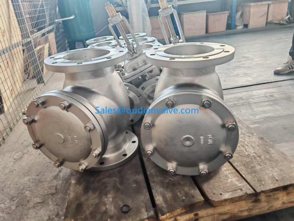
Mechanics and Performance of Swing Check Valves
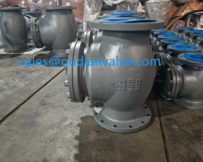
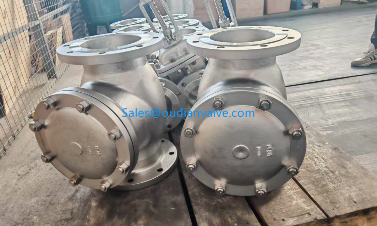
Swing check valves utilize an internal disc attached to a top-mounted hinge pin or pivot arm that swings through an arc to open and close. Forward fluid velocity pushes the swinging disc upward away from the orifice, providing an unobstructed waterway that closely matches the full internal diameter of adjoining pipework. This streamlined internal geometry produces low resistance to flow, making the swing check valve an efficient choice for high-volume liquid systems.
Closing depends primarily on gravity pulling the swung flap back down as flow velocity decelerates, aided by reverse pressure forcing the disc flat against the seat. Because the disc travels across a wide mechanical arc, rapid flow reversal can drive the disc into the valve seat with considerable impact. Exterior counterweights or lever-and-weight assemblies can assist disc closure timing, though care must be taken to balance response speed against line turbulence.
These units function reliably in horizontal piping arrangements where gravity assists downward flap seating without mechanical binding. When applied in vertical runs, flow must always travel upward so gravity can reseat the disc during flow stoppage. Applying swing check designs requires sufficient continuous flow velocity to hold the disc fully open against its travel stop, avoiding internal disc chatter.
- Full-port fluid passages reduce frictional resistance and overall pumping energy expenditure across broad piping networks.
- Mechanical hinge pins positioned outside the primary waterway isolate pivot bearings from aggressive debris accumulation.
- Removable bonnet caps permit direct internal inspection, seat reconditioning, and disc replacement without pipe removal.
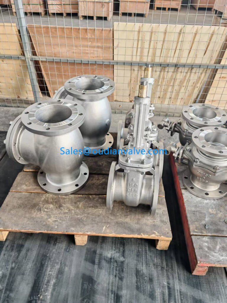
Ball, Poppet, and Disc Check Valve Configurations
Ball check valves employ a spherical closure element that moves freely within an angled or vertical chamber inside the valve body. Upstream fluid pressure lifts the spherical ball off the circular seat, guiding it into an internal recess where media can stream past the lower boundary. When forward velocity stops, gravity or fluid backpressure forces the sphere down into the conical seat, producing a tight seal even in systems carrying viscous liquids or suspended particulates.
Disc check valves and poppet check styles incorporate flat plates or guided plugs supported by an inline spring assembly. The spring maintains constant tension against the closure mechanism, holding it seated until upstream line pressure exceeds the predetermined spring rating. Because the disc travels a very short linear distance along a central guide pin, disc check valves close much faster than swinging models, significantly decreasing reverse flow slip.
These compact designs operate effectively in both horizontal and vertical piping lines because the internal spring eliminates complete reliance on gravity for closing motion. Wafer-style disc check valves fit cleanly between companion pipe flanges, occupying minimal axial length within tight skid packages. Spring-assisted ball and poppet variants provide dependable shutoff across chemical dosing lines, compressed air runs, and high-cycling hydraulic loops.
| Tipul de supapă | Closure Motion | Spring Assist | Primary Strengths |
| Ball Check | Spherical lift | Opțional | Handles thick or slurry-laden liquids without mechanical binding. |
| Poppet Check | Guided plug | Standard | Delivers rapid response and tight shutoff in compact pneumatic runs. |
| Disc Check | Linear plate | Standard | Fits narrow wafer spaces and minimizes fluid slippage during flow decay. |
Silent Check and Piston Check Valve Designs
Silent check valves use an internal disc guided along a center shaft and preloaded with a durable stainless steel spring. As fluid slows toward a stagnation point, the spring expands to push the disc toward the seat before the fluid column can reverse direction. By achieving closure at or near zero liquid velocity, the silent check valve suppresses destructive hydraulic pressure spikes commonly generated by sudden fluid reversal.
Piston check valves incorporate a heavy sliding piston operating within a precision-machined internal cylinder that functions as a hydraulic damper or dashpot. Upstream flow pushes the piston upward into the cylinder pocket, while fluid trapped inside the cavity vents through controlled clearances. During sudden flow fluctuations, the dashpot arrangement prevents rapid slamming, cushioning movement through controlled fluid displacement.
These advanced non-return valves serve critical functions in high-head pumping systems, building service risers, and pulsating steam supply headers. Silent check assemblies excel where acoustic suppression and structural pipe protection remain paramount operational goals. Piston check models provide exceptional durability in severe high-pressure service where repetitive cycling would rapidly damage lighter mechanical linkages.
Silent Check Features
Center-guided disc assemblies utilize calibrated compression springs to complete mechanical closure prior to flow reversal. This rapid response protects mechanical couplings and building structures from acoustic shock waves.
Piston Check Features
Integrated dashpot cavities cushion piston travel against severe hydraulic pulsations and irregular compressor discharges. Rugged metallic seating surfaces withstand extreme thermal cycling and high differential pressures.
Check Valve Applications Across Core Fluid Systems
Piping systems across commercial and manufacturing operations rely on non-return valves to preserve mechanical components and stabilize flow paths. In water distribution networks and municipal lift stations, check valves installed on pump discharge lines prevent reverse spinning of impellers when drive motors de-energize. Isolating shutdown pumps from dynamic manifold pressures prevents reverse flow from draining elevated storage reservoirs back through inactive equipment.
HVAC systems apply spring-loaded check valves throughout chilled water loops, boiler feedwater headers, and multi-zone hydronic networks. These valves prevent thermal siphoning during periods of low heating demand and eliminate cross-circulation between parallel operating chillers. Compressed air and industrial gas lines use poppet check valves on compressor discharge heads to maintain accumulator tank pressure while relieving pressure off unloaded pump heads.
In refining, petrochemical processing, and oil gas extraction, check valves protect multi-phase separators, injection headers, and product pipelines from dangerous contamination cross-flows. Food beverage manufacturing facilities utilize polished sanitary check valves with food-grade elastomeric seals to prevent backward contamination in process pasteurizers and batch mixing vessels. Each industry relies on predictable flow-activated sealing to maintain batch purity, system efficiency, and process stability.
HVAC Systems
Spring-loaded check valves isolate parallel circulating pumps, control thermal distribution across building risers, and eliminate ghost circulation in inactive hydronic loops.
Oil and Gas Lines
Heavy-duty forged non-return valves manage volatile hydrocarbons, prevent process contamination between converging headers, and resist corrosive sour gas conditions.
Food and Beverage
Crevice-free sanitary check valves maintain sanitary separation in milk pasteurizers, beverage filling manifolds, and automated cleaning distribution headers.
Advantages of Automatic Non-Return Check Valves
Check valves operate autonomously without sensory instrumentation, external pneumatic actuators, or manual operating personnel. By utilizing the intrinsic energy within the moving fluid column, these devices perform immediate shutoff functions during electrical outages or automated control failures. This self-contained operational model provides continuous mechanical line protection under dynamic operating circumstances.
Employing the right check valve configuration lowers overall equipment lifecycle costs by shielding expensive centrifugal pumps, positive displacement blowers, and flow meters from destructive backward surges. Preventing reverse impeller rotation stops shaft breakage, seal blowout, and motor overspeed damage during abrupt system trip events. Minimizing reverse flow leakage also preserves fluid prime in suction lines, shortening pump restrike intervals and lowering startup torque loads.
Furthermore, contemporary spring-assisted check valves significantly reduce acoustic pollution and structural vibrations in commercial buildings and manufacturing plants. Controlling reverse fluid acceleration avoids severe piping movement, decreasing stress fatigue on structural pipe hangers, welded joints, and mechanical expansion couplings. The resulting line stability extends the operating intervals between routine piping maintenance overhauls.
Avantaje
- Requires no auxiliary electrical power, control wiring, or automated positioning signals to operate.
- Protects rotating pumps and upstream equipment against destructive backpressure and reverse driving forces.
- Maintains system prime across suction lines, allowing rapid pump restarts without manual air purging.
Limitări
- Internal moving components remain concealed inside the valve body, complicating visual status checks.
- Introduces continuous hydraulic head loss across the piping system compared to open gate valves.
- Low flow velocity can induce rapid disc fluttering, accelerating pivot pin and seat degradation.
Operational Limitations and Application Boundaries
Despite their operational value, check valves introduce inherent mechanical constraints that require careful piping integration. Because the closure element permanently occupies the fluid path, the valve creates continuous frictional resistance and localized pressure drop. In low-pressure gravity drainage systems or low-head water transfer systems, this permanent head loss can noticeably degrade overall hydraulic efficiency.
Internal flow components also remain susceptible to process media fouling, suspended solids accumulation, and fibrous media entanglement. Particulates trapped between the sealing face and the valve seat prevent complete closure, resulting in reverse flow seepage that undermines line isolation. Mineral scaling and corrosive deposition can also bind internal hinge pins, pivot bushings, or linear shaft guides, locking the valve in an open or closed state.
Operating a check valve significantly below its design velocity presents severe mechanical risks. If forward flow lacks sufficient momentum to hold the internal disc firmly against its travel stop, the disc oscillates rapidly within the turbulence zone. This sustained fluttering accelerates wear on hinge bushings, guide shafts, and sealing surfaces, potentially leading to mechanical detachment of internal components.
Operating check valves in systems with pulsating flow or insufficient fluid velocity causes persistent disc fluttering. Mechanical oscillation accelerates hinge pin wear and can cause fatigue failure of internal closure elements.
Critical Orientation and Piping Installation Factors
Correct spatial positioning dictates whether a check valve operates smoothly or experiences premature mechanical failure. Every check valve body displays an external directional arrow cast or stamped into the exterior metal wall, indicating the intended direction of forward fluid flow. Installing a valve in reverse orientation completely blocks process flow, generating dangerous overpressure on upstream pumping equipment.
Piping orientation relative to gravity significantly influences valve selection and performance. Standard swing check valves and gravity-actuated ball check valves must remain restricted to horizontal pipe runs or vertical runs featuring upward flow. Installing gravity-dependent valves in downward flow configurations prevents the internal closure member from seating, allowing unimpeded reverse flow across the entire line.
Upstream fluid turbulence represents another major cause of unstable valve performance. Check valves installed directly downstream of pipe elbows, throttling control valves, or centrifugal pump discharges experience chaotic flow profiles that induce severe disc vibration. Placing a check valve along a straight section of straight pipe away from disturbing fittings promotes laminar flow and stable disc positioning.
- Inspect the flow direction arrow cast into the valve body to verify alignment with forward system flow.
- Confirm that piping inclination matches the design limits of the chosen valve, especially for gravity-dependent models.
- Locate the valve downstream from pumps and pipe fittings along straight pipe to avoid irregular fluid eddies.
- Verify adequate surrounding clearance to allow future bonnet removal, internal seat inspection, and hinge pin servicing.
Water Hammer Prevention and Dynamic Pressure Surge Control
Water hammer is a violent hydraulic pressure wave generated when a moving fluid column undergoes sudden, uncontrolled deceleration or directional reversal. In pumping networks lacking proper check mechanisms, power interruptions cause forward flow to stop and quickly reverse toward the pump discharge port. When a slow-closing swing check valve finally hits its seat after reverse flow has gathered velocity, the instantaneous stoppage creates destructive pressure surges.
These intense shock waves travel through the piping system at sonic velocities, generating loud metallic knocking sounds, rattling pipe hangers, and stressing pipe joints. Over prolonged periods, unchecked water hammer ruptures pipe walls, splits flanged connections, destroys delicate flow meters, and fractures pump volutes. Selecting check valves engineered for dynamic closure characteristics provides the first line of defense against these catastrophic hydraulic events.
Silent check valves and nozzle-style check valves excel at mitigating pressure transients through spring-assisted fast closure. The internal spring begins driving the disc toward the valve seat the instant forward flow deceleration begins, completing closure at the exact point of zero velocity. Closing before reverse flow velocity develops eliminates the kinetic energy spike that triggers water hammer, protecting mechanical systems from structural failure.
Water hammer occurs when reverse flow gathers momentum before a check valve completely seals. Spring-assisted silent valves close at zero velocity, halting the fluid column before destructive shock waves can form.
Troubleshooting Common Check Valve Operational Faults
Identifying operational faults in non-return valves requires correlating external line symptoms with internal mechanical behavior. Because check valve components remain concealed within pressurized pipe casings, diagnosing issues relies on pressure gauge monitoring, acoustic listening rods, and thermal imaging. Systematic troubleshooting isolates mechanical failures early, avoiding extensive downtime across connected utility lines.
Backflow leakage is the most frequent operational complaint encountered in industrial fluid systems. When downstream pressures steadily decrease after pump shutdown, fluid is slipping backward past the valve seat. This leakage typically stems from particulate deposition on sealing perimeters, elastomeric O-ring degradation from aggressive chemicals, or mechanical scoring across metallic valve seats caused by high-velocity abrasive slurries.
Audible chattering or metallic rattling indicates that the internal disc is continuously bouncing against its travel stops or seat ring. This symptom reveals severe undersizing of fluid velocity, where the line fails to generate enough dynamic lift to pin the disc open. Conversely, severe single-impact slamming during pump shutdown indicates sluggish closing response, signaling weak springs, pivot pin binding, or an incorrect valve style for high-head applications.
Symptoms and Causes
- Continuous backflow leakage indicates seat scoring, particulate buildup, or chemical seal breakdown.
- Rhythmic mechanical chattering reveals low fluid velocity, turbulent eddies, or oversized valve bodies.
- Loud closing slam indicates delayed disc travel, worn return springs, or inappropriate swing designs.
Corrective Actions
- Flush line debris, recondition metallic seats, or replace worn elastomeric sealing components.
- Resize the valve to match operational line velocity rather than nominal pipe diameter.
- Install spring-assisted silent check designs or dampening dashpots to accelerate closure timing.
Choosing the Right Check Valve for Piping Systems
Selecting the optimal check valve requires an evaluation of the physical media, operating environment, and system hydraulics. Specifying a valve based solely on pipe connection size often results in an oversized mechanism that suffers from premature wear, seat damage, and continuous chatter. Sizing must account for normal operating flow rates, minimum flow thresholds, and peak surge velocities across the piping schedule.
Media compatibility determines both the internal trim materials and the overall body construction. Clean municipal water systems perform well with ductile iron bodies fitted with bronze or stainless steel internals and resilient EPDM seals. In contrast, corrosive chemicals, hydrocarbons, and high-temperature steam lines require forged carbon steel, alloy steels, or fluoropolymer seat linings to withstand chemical erosion and thermal degradation.
Piping layout geometry, allowable head loss margins, and closing speed requirements define the ideal mechanical valve style. Pumping networks with high discharge heads demand rapid-closing silent or nozzle check valves to suppress destructive shock waves. Low-head gravity systems benefit from full-port swing check valves that minimize pumping resistance, provided horizontal orientation or upward vertical flow can be accommodated.
Media and Materials
Match body metallurgy and internal elastomer trims to fluid chemistry, temperature ranges, and suspended solids content to prevent premature chemical corrosion and seat erosion.
Velocity Sizing
Size valve mechanisms according to continuous flow velocity rather than matching nominal pipe size to maintain full disc lift and avoid damaging low-velocity fluttering.
Closing Dynamics
Evaluate potential reverse flow acceleration during pump trips to select closure mechanisms, such as spring-assisted discs, that eliminate water hammer in high-head loops.
Frequently Asked Questions About Check Valves
Can check valves be installed vertically?
Check valves can be installed vertically only when forward flow travels upward and the valve design permits it. Spring-assisted disc, silent, and ball check valves handle upward vertical runs effectively, whereas downward vertical flow prevents valves from sealing correctly against reverse flow.
What causes a check valve to chatter?
A check valve chatters when line velocity is insufficient to hold the internal disc firmly against its travel stop. This low dynamic pressure allows the closure element to repeatedly strike the valve seat or internal stops as fluid eddies fluctuate.
How does a check valve differ from a control valve?
A check valve operates self-sufficiently using line pressure differentials to prevent reverse flow without external intervention. Control valves require external actuators, sensors, and positioning signals to modulate flow rates, pressure levels, or fluid temperatures.
Why does a check valve leak backward?
Backward leakage occurs when debris lodges between the closing disc and the seat, preventing full mechanical closure. Physical scoring from abrasive particles, chemical degradation of resilient seals, or mechanical binding of hinge pins also allows fluid slip.
How does a silent check valve stop water hammer?
A silent check valve uses a calibrated internal spring to close the disc at the precise moment forward fluid velocity drops to zero. By sealing before reverse flow can gather momentum, the valve prevents sudden kinetic energy shocks that trigger water hammer.
How often should check valves undergo inspection?
Inspection frequency depends on fluid corrosiveness, operating cycle counts, and media cleanliness. High-cycling lines or abrasive slurry applications benefit from routine visual checks every few months, while clean water lines require maintenance only when symptoms appear.
Maintaining Fluid Line Integrity
Selecting and maintaining the appropriate check valve establishes dependable, automatic protection against reverse flow throughout complex piping networks. Aligning valve geometry with dynamic fluid velocities, media characteristics, and orientation limits extends operational lifecycles and shields rotating pumps from mechanical shock. Routine monitoring of pressure differentials, acoustic levels, and seat integrity helps preserve smooth, uninterrupted process performance across municipal and industrial fluid systems.