


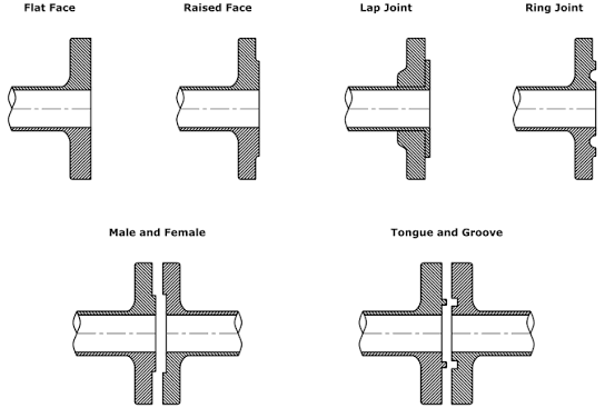
Types of Flange Faces – FF, RF, RTJ, T&G and MF
Types of Flange Faces – FF, RF, RTJ, T&G and MF
In industrial piping, types of flange faces – FF, RF, RTJ, T&G and MF dictate how a bolted joint compresses its gasket and maintains pressure containment under operating stresses. The flange face is the machined contact surface that transfers bolt preload into gasket compression, establishing an impermeable barrier against line fluid. Selecting the correct face style prevents localized flange rotation, mechanical cracking, and catastrophic seal failure across low-pressure utilities and severe-duty processing lines.
Operational stability depends on the combined performance of mating face geometry, compatible gasket construction, bolt metallurgy, and precise axial alignment. Mismatched mating faces or inappropriate gasket selections compromise the contact stress distribution, leading to joint relaxation and leakage. Engineering codes establish strict parameters for these connections to sustain mechanical integrity across thermal cycles and dynamic pipe vibrations.
Fundamentals of Flange Faces and Joint Integrity
A flange face serves as the critical mating boundary between adjacent piping spools, process vessels, or inline valves. When tightening bolts, the resulting mechanical load compresses the soft gasket material into microscopic imperfections across the machined face. If the face geometry fails to support the required seating stress, process fluid can escape along the contact boundary.
Maintaining joint integrity requires strict coordination between four interdependent elements: the face profile, the gasket material, the bolting torque, and the axial pipe alignment. Poor alignment introduces uneven stress concentrations across the gasket circumference, causing localized crushing on one side and insufficient seating stress on the other. Appropriate face selection accommodates specific operating pressures and thermal expansions without overstressing either the gasket or the flange hub.
Flange face surface finishes feature controlled phonographic or concentric spiral serrations that grip non-metallic gasket materials, preventing radial blowout under internal pressure.

Flat Face (FF) Flanges
Flat face flanges feature a continuous, smooth contact plane extending from the internal pipe bore all the way to the outer edge of the flange. Because the contact plane covers the entire surface, bolt holes pass directly through the sealing face area. When bolted, flat face flanges require full-face gaskets that span the identical diameter and include corresponding bolt holes.
This planar configuration distributes bolt preload over a broad surface area, resulting in lower gasket seating stress for a given torque value. Full-face elastomeric or non-metallic sheet gaskets are standard, as metallic gaskets cannot generate sufficient seating compression over such large surface areas. Typical applications include low-pressure water systems, fire protection lines, wastewater treatment plants, and pump connections constructed from brittle materials.
Avantaje
- Even contact area eliminates bending moments across the flange hub.
- Reduces the risk of cracking brittle cast iron, bronze, or plastic equipment.
- Simple full-face gasket alignment guided by bolt hole penetration.
Limitări
- Requires large bolt loads to achieve sufficient gasket seating stress.
- Restricted to low-pressure and moderate-temperature applications.
- Unsuitable for hazardous, toxic, or high-pressure hydrocarbons.
Flat face designs are standard on equipment casings where mechanical deflection must remain minimal to protect cast structures. Installation requires sequential cross-pattern torqueing using calibrated tools to maintain uniform compression across the expansive gasket surface.

Raised Face (RF) Flanges
Raised face flanges concentrate bolt loading onto a localized contact zone that elevates above the bolt circle diameter. The raised face height provides a smaller, well-defined surface that maximizes compressive force against the gasket. Bolt holes sit outside this elevated plane, allowing ring-style gaskets to center themselves neatly inside the inner diameter of the bolt circle.
The raised geometry focuses mechanical energy directly into the gasket area, achieving high seating stresses with moderate bolting effort. Compatible sealing materials include compressed non-asbestos fiber sheets, spiral wound gaskets with inner and outer rings, and flexible graphite-faced Kammprofile gaskets. These assemblies serve as the primary standard across chemical processing plants, utility steam distribution, and petroleum refining networks.
Avantaje
- High compressive stress achieved on the gasket with lower bolt preload.
- Accommodates a broad range of metallic, semi-metallic, and non-metallic gaskets.
- Ring gaskets can be replaced without complete disassembly of surrounding piping.
Limitări
- Tightening generates a bending moment on the flange neck and pipe wall.
- Excessive bolt torque can deform the flange ring or crush the gasket element.
- Unsuitable for direct connection to brittle cast iron equipment flanges.
Standard elevated face dimensions vary depending on the pressure rating of the joint. Lower pressure ratings utilize a standard elevation height, while higher pressure classes employ a thicker elevated pad to withstand severe mechanical strains without structural warping.

Bolting Flat Face to Raised Face Flanges
Connecting a flat face flange directly to a raised face flange creates a severe mechanical mismatch that violates fundamental engineering practices. When a raised face presses against a flat face, the gap created outside the raised pad leaves the outer flange section unsupported. As bolts outside the raised area are torqued down, extreme bending stresses develop across the cast or forged body.
This uneven leverage frequently cracks brittle equipment flanges, such as cast iron pumps, valves, and strainers commonly found in water service. If a connection between differing styles becomes unavoidable, the raised face of the steel flange must be machined completely flat to restore planar contact across the entire diameter. Alternatively, hard spacer rings matching the gap height can prevent localized flange rotation, though replacing the component with a matched flat face spool provides greater reliability.
Never bolt a raised face steel flange to a cast iron flat face flange without eliminating the step, as the bending moment readily cracks brittle cast iron around the bolt holes.
Ring Type Joint (RTJ) Flanges
Ring type joint flanges incorporate deep, precisely machined trapezoidal grooves cut directly into an elevated face surface. Sealing occurs through metal-to-metal contact as an oval or octagonal metallic ring gasket deforms plastically into the angled groove walls. The gasket material must remain softer than the flange metal to allow plastic deformation without scoring the groove surfaces.
As the joint bolts tighten, mechanical wedge action creates high contact pressures along narrow lines on each face of the ring. When system pressure rises, internal fluid pushes outward against the metal ring, increasing contact stress against the outer groove wall in a self-energizing manner. These joints operate in high-pressure oil and gas production, offshore platforms, high-temperature hydrocarbon refining, and power generation boilers.
Avantaje
- Exceptional sealing reliability under extreme operating pressures and temperatures.
- Metal-to-metal contact provides robust blow-out resistance for severe services.
- Internal line pressure increases sealing effectiveness through natural wedging action.
Limitări
- Machined grooves can trap dirt, requiring meticulous cleaning before assembly.
- Damaged groove walls require costly remachining or complete flange replacement.
- Flanges must be spread wide axially to remove or insert rigid metallic rings.
Octagonal ring gaskets provide superior sealing capability compared to traditional oval designs by providing planar surface engagement along the groove chamfers. Proper installation requires verifying that groove surfaces are completely free of burrs, corrosion, or foreign particulates prior to bolt tightening.

Tongue and Groove (T&G) Flanges
Tongue and groove flanges function as matched pairs where one mating face features a raised continuous ring (the tongue) and the opposing face features a matching recess (the groove). The gasket sits entirely inside the recessed channel, matching the precise width and depth of the groove. When the halves mate, the tongue enters the groove and applies compressive force exclusively across the confined gasket area.
This design prevents gasket blowout because the internal and external channel walls restrict lateral movement under pressure. The mechanical geometry automatically centers the gasket during fit-up, eliminating common misalignments that cause leaks. Tongue and groove joints are selected for vacuum systems, ammonia refrigeration systems, hazardous chemical services, and applications where fluid contact with outer gasket edges must be prevented.
Avantaje
- Total gasket confinement eliminates radial blowout under pressure spikes.
- Inherent self-centering ensures exact gasket placement during installation.
- Narrow contact surface area requires lower bolt torque to seat the seal.
Limitări
- Requires stocking two distinct flange geometries rather than identical mating parts.
- Maintenance requires axial pipe separation to disengage the extended tongue.
- Groove cleaning can prove difficult when old gasket materials adhere to bottom surfaces.
Because the gasket does not directly contact the surrounding atmosphere, tongue and groove configurations reduce the likelihood of atmospheric corrosion attacking the seal perimeter. Non-metallic sheet gaskets, compressed graphite, or solid flat metal rings are typical choices for these confined chambers.
Male and Female (MF) Flanges
Male and female flanges also operate as matched pairs, utilizing an elevated section and a corresponding recess across the mating faces. The male flange features a raised contact pad that extends beyond the standard raised face plane, while the female flange has a matching shallow depression. Unlike tongue and groove designs, the female recess extends outward without an inner retaining wall at the bore.
The gasket sits within the female recess, which locates the sealing element accurately while providing external blowout resistance along the outer perimeter. Non-metallic and semi-metallic gaskets fit inside the female cavity, protected from external mechanical disturbances. MF flanges are standard in medium-to-high pressure services, hydraulic fluid power lines, and specialty heat exchanger nozzle connections.
Avantaje
- Female recess maintains gasket alignment during joint assembly.
- Outer perimeter wall reduces the risk of radial gasket displacement.
- Higher sealing capability than conventional raised face connections.
Limitări
- Incompatible with standard raised face or flat face components.
- Inventory management is more complex due to pairing requirements.
- Piping flexibility is necessary to separate faces during gasket replacement.
While sharing similarities with tongue and groove flanges, male and female joints offer larger contact areas that distribute bolt loads across a slightly wider gasket footprint. This provides balanced seating stresses suitable for fluctuating thermal regimes.
Comparison and Industry Standards
Flange specifications follow standardized engineering codes to govern face dimensions, machining tolerances, and pressure-temperature ratings. Prominent international codes include ASME B16.5 for piping up to 24 inches, ASME B16.47 for large diameter lines, and EN 1092-1 for metric European piping systems. Standards define specific face heights, serration depths, and groove dimensions, but components manufactured under differing international codes are not interchangeable.
| Face Design | Gasket Type | Aplicații comune | Sealing Reliability | Installation Considerations |
| Flat Face | Full-Face Sheet | Water Utilities | Moderat | Prevent uneven bolt stress across full face |
| Raised Face | Ring or Spiral | Process Piping | Ridicat | Center gasket evenly within the bolt circle |
| Ring Type Joint | Solid Metallic | Oil and Gas | Foarte ridicat | Inspect groove walls for scratches or dirt |
| Tongue & Groove | Confined Ring | Chemical Service | Foarte ridicat | Verify clean recess before tongue engagement |
| Male & Female | Recessed Ring | Heat Exchangers | Ridicat | Allow adequate pipe travel for face separation |
Selecting the Right Flange Face
Specifying a flange face requires evaluating process parameters, mechanical configurations, and environmental risks across the system lifecycle. A mismatched face selection can lead to continuous fugitive emissions, gasket extrusion, or structural cracking under thermal transients. Engineering teams evaluate several primary parameters when finalizing piping specifications:
- Pressure and Temperature Profile: Severe ratings mandate ring type joints, while standard utility conditions use flat or raised faces.
- Process Fluid Toxicity and Flammability: Hazardous chemicals require confined configurations like tongue and groove or male and female faces to eliminate blowout risks.
- Equipment Material Compatibility: Cast iron, fiberglass, or bronze components require flat face connections to prevent bending fractures.
- Piping Maintenance Flexibility: Raised face joints allow simple lateral gasket replacement without extensive axial pipe spreading.
- Leakage Tolerance: Zero-tolerance fugitive emission lines favor metallic ring seals or fully confined gasket chambers.
Each design balances sealing capability against operational practicality. Where systems experience extensive maintenance cycles, standardized raised face connections offer optimal serviceability without requiring complex paired component tracking.
Inspection, Installation, and Mistakes to Avoid
Reliable joint performance depends entirely on careful pre-assembly checks and methodical bolt tightening procedures. Scratches across a flange face that cross the radial sealing path provide immediate leak paths that no amount of bolt torque can overcome. Technicians should execute standardized installation sequences to preserve joint integrity:
- Inspect face machining for gouges, corrosion pits, and serration defects prior to cleaning the contact area.
- Confirm gasket dimensions, metallurgy, and filler material match the flange rating and process specifications.
- Check flange alignment for angular parallel alignment and axial bolt hole registration without using excessive leverage.
- Apply clean thread lubricant to stud threads and nut bearing surfaces to maintain consistent friction coefficients.
- Tighten fasteners in alternating star patterns across multiple torque increments to distribute compressive stresses uniformly.
Common field errors include reusing previously compressed gaskets, combining mismatched flange styles without transition spools, and using improper bolt lengths that leave threads unengaged. Gaskets deform permanently upon initial compression, meaning reused gaskets cannot adapt to face serrations during second assemblies.
| FLANGE FACE TYPE | |||||
| Characteristics | Flat face | Raised face | Ring-Type Joint | Tongue and Groove | Male and female |
| Sealing area | Big | Mediu | Little | Little | Little |
| Face sealing area | Inner to outer diameter | Inside diameter to outside diameter of highlighted area | Groove in the face | Groove in the face | Groove in the face |
| Interval de presiune | Low pressure | General | General. High pressure | Specific. High pressure | Specific. High pressure |
| Pressure class | 125#, 250# | All. Up to 2500#. | 900# | All. Up to 2500#. | 900# |
| Interval de temperatură | Low temperatures | General | General | General. Extreme conditions. | General. Extreme conditions. |
| Type of joint | Soft. non metallic | Non-metallic, semi-metallic. | Hard. Metal-metal. | Non-metallic, semi-metallic. | Non-metallic, semi-metallic. |
Frequently Asked Questions
Why is connecting a flat face flange to a raised face flange discouraged?
Bolting a flat face flange to a raised face flange leaves the outer portion of the flat flange unsupported. When bolts are tightened, bending stresses develop that can crack brittle materials such as cast iron or plastic. If such a connection is unavoidable, the raised face must be machined flat or fitted with a full-face support ring.
What distinguishes an octagonal RTJ gasket from an oval RTJ gasket?
Octagonal ring gaskets have flat sealing facets that establish planar contact with the angled walls of the flange groove. Oval gaskets make curved line contact against the groove walls, which requires higher seating load to seal. Octagonal rings provide higher sealing efficiency and fit modern standard RTJ grooves.
How does a tongue and groove flange differ from a male and female flange?
A tongue and groove flange utilizes a narrow tongue that enters a matching groove with both inner and outer retaining walls. A male and female flange features a broader raised face that fits into a recessed pocket lacking an inner retaining wall at the bore. Tongue and groove designs offer total gasket confinement, whereas male and female faces provide external perimeter retention.
Can spiral wound gaskets be used on flat face flanges?
Standard spiral wound gaskets designed for raised face flanges should not be installed on flat face cast iron flanges. The small contact area concentrates high compressive stress that can distort the flange or crack brittle equipment. Full-face sheet gaskets that distribute loading across the entire surface are standard for flat face assemblies.
Summary of Flange Face Selection
Choosing between flat face, raised face, ring type joint, tongue and groove, and male and female designs determines the long-term reliability of a bolted piping connection. Matching the face geometry to the operating pressure, temperature limits, equipment metallurgy, and compatible gasket materials prevents mechanical failure and unwanted fluid release. Methodical surface inspection, parallel flange alignment, and controlled bolt tightening ensure dependable joint integrity across all industrial piping systems.