

Globe Valve Parts and Components: Diagram and Functions
Operating pressure, service temperature, fluid corrosiveness, and cycle frequency determine the appropriate component styles and materials for an assembly. Reviewing internal trim, stem sealing methods, and joint designs prior to installation protects systems against fugitive emissions and unexpected downtime.
What Are the Main Parts of a Globe Valve?
The primary assembly of a globe valve combines pressure-retaining casings with movable internal mechanisms that govern fluid passage. While simplified descriptions reference only five core elements, industrial service requires evaluating auxiliary seals, mechanical joints, and operating devices.
Dividing the assembly into functional engineering groups clarifies how each component contributes to pressure containment, mechanical movement, and fluid isolation.
Pressure Boundary
The body, bonnet, and joint gaskets form the external pressure-containing shell that directs line media safely through the system.
Motion and Control
The operating wheel, external actuator, valve stem, and disc transfer mechanical force into precise linear throttling movement.
Sealing and Trim
The seat ring, closure face, packing rings, and wetted trim components maintain tight shutoff and prevent atmospheric leakage.
Elementary summaries frequently reduce a globe valve to its body, bonnet, stem, disc, and seat. That five-part framework provides a basic conceptual foundation, but real piping systems demand strict verification of packing integrity, gasket compatibility, trim metallurgy, and actuation torque.
Omitting secondary components during engineering review creates substantial operating risks. Unspecified stem packing materials or incompatible bonnet joint seals can cause external leaks even when the main cast body meets project pressure ratings.
Globe Valve Parts Diagram: Structural Arrangements
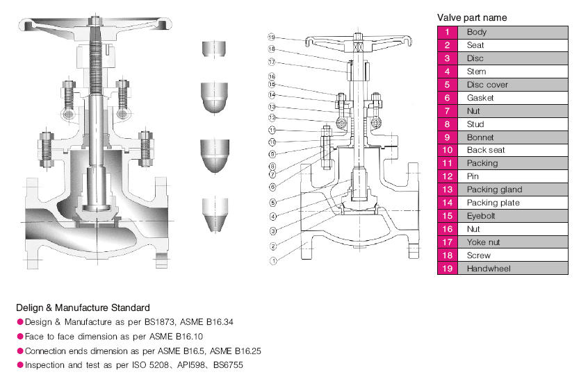
A globe valve structural diagram illustrates how static pressure shells, internal fluid passages, and dynamic driving elements connect inside the assembly. Tracing these connections reveals how external mechanical input translates into internal fluid regulation.

The operating device attaches to the upper end of the stem, which passes through the packing gland housed within the bonnet neck. The lower end of the stem secures the closure disc, positioning it directly above the stationary body seat.
Evaluating an internal valve diagram across three functional planes—the pressure shell boundary, the linear motion transfer line, and the static-plus-dynamic sealing barrier—simplifies maintenance inspections and parts ordering.
The pressure shell boundary marks the structural envelope containing line fluid under pressure. The motion transfer line traces force transmission from the operator down to the closure member. The sealing barrier defines internal shutoff across the seat and external containment through the stem packing and bonnet gasket.
Analyzing these structural layers prevents confusing basic operational movement with complete fluid isolation. A properly aligned stem cannot compensate for an eroded seat ring, and a robust body casting cannot prevent leakage across an improperly compressed bonnet gasket.
Summary Table of Globe Valve Parts and Functions
Every component in a globe valve performs a specific mechanical task that influences system reliability, maintenance frequency, and quotation scope. Reviewing these roles helps technical teams verify specifications before procuring equipment.
The following table outlines the primary assembly components, their engineering classification, their mechanical action, and key specification checkpoints.
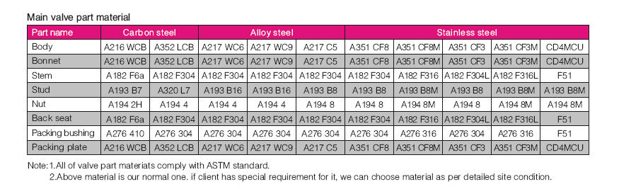
| Part | Assembly Group | Primary Function | Engineering Impact |
| Corp | Pressure Shell | Retains Pressure | Defines flow path, end connection, pressure rating, and structural envelope. |
| Capotă | Pressure Shell | Covers Chamber | Provides internal access and houses stem guidance and packing chambers. |
| Disc | Flow Closure | Regulates Passage | Determines shutoff tightness, throttling contour, and resistance to cavitation. |
| Scaun | Internal Seal | Provides Contact | Forms stationary shutoff boundary and withstands continuous fluid impingement. |
| Tulpina | Motion Transfer | Transmits Force | Converts rotational drive into linear thrust and maintains axial alignment. |
| Packing | Stem Seal | Restricts Emission | Prevents fugitive atmospheric leakage along the dynamic stem surface. |
| Gasket | Joint Seal | Closes Flange | Maintains static joint integrity between body and bonnet under pressure cycles. |
| Trim | Internal Wetted | Governs Resistance | Dictates corrosion resistance, erosion durability, and throttling service life. |
| Handwheel | Operațiune | Controls Stem | Establishes manual leverage, stroke precision, and operator control torque. |
Using this table assists engineering teams in identifying potential design mismatches early. Addressing component scope before manufacturing prevents common ordering mistakes, such as specifying standard trim for corrosive service or selecting manual wheels where high differential pressure demands mechanical gear operators.
Pressure Boundary Components: Body, Bonnet, and Joint Gaskets
Pressure boundary components form the external containment shell of the valve. They must withstand internal fluid pressure, pipeline stresses, and thermal expansion while preventing leakage to the outside environment.
The valve body serves as the main structural casting or forging. It incorporates the inlet and outlet ports, supports the internal seating geometry, and establishes the internal path that directs fluid through the throttling orifice.
Because the body forces fluid through a tortuous S-shaped passage, it generates greater flow resistance than straight-through gate or ball designs. Selecting the proper body pattern—standard tee, inclined Y-pattern, or ninety-degree angle—helps balance pressure drop against layout constraints.
- Body material selection must match line media compatibility and temperature limits.
- End connections must align with pipeline flange, socket weld, or threaded requirements.
- Pressure class ratings must account for peak operational pressures and design safety factors.
- Internal port diameters must accommodate calculated flow coefficients without excessive restriction.
- Face-to-face dimensions must conform to established industrial piping envelope standards.
The bonnet attaches directly to the body, serving as a removable cover for internal access and maintenance. It contains the stuffing box, supports the stem bushings, and sustains fluid pressure along its internal face.
Common bonnet joints include bolted configurations for standard industrial service, threaded assemblies for small utility lines, welded joints for leak-critical chemicals, and pressure-seal designs for high-pressure power generation. Each configuration demands distinct maintenance procedures and bolting torque protocols.
The body-bonnet gasket seals the mechanical joint between these two heavy structural components. Gasket materials range from flexible graphite sheet to spiral-wound metallic composites and solid metal rings, selected according to service temperature, chemical aggressiveness, and joint style.
Motion and Flow-Control Components: Stem, Disc, and Actuator
Motion and flow-control components convert external operating energy into internal linear positioning. These dynamic elements govern throttling sensitivity and determine shutoff performance under changing process demands.
The operating interface provides the mechanical power needed to position the internal mechanism against line pressure forces. While manual handwheels suffice for modest diameters and moderate line pressures, larger valves or high differential pressures require mechanical gearboxes or automated actuators.
Manual Handwheel Drive
- Provides tactile feedback during throttling
- Eliminates external utility dependencies
- Requires physical operator access on site
- Demands high manual effort under load
Automated Actuator Drive
- Enables remote automation and rapid response
- Delivers consistent thrust under differential loads
- Integrates with plant control loops
- Requires external pneumatic or electric power
The stem transfers linear or rotary motion from the operating device to the closure member. Rising stem designs provide visual indication of valve opening position, while rotating, non-rising configurations suit tight physical envelopes.
Stem machining quality directly affects packing longevity and operational torque. A surface with fine micro-finish reduces friction against the packing rings, while precision threads prevent galling under continuous throttling duty.
The disc, or plug, serves as the movable barrier that seats against the stationary orifice. Flat-faced discs suit utility on-off isolation, needle plugs offer precise control across low flow rates, and parabolic contoured plugs provide linear or equal-percentage throttling curves.
Contoured plugs disperse fluid energy gradually, reducing localized erosion during prolonged throttling. Choosing an improper disc contour can result in unstable flow control, hunting in automated loops, or severe seat chatter.
Sealing Components: Seat Interface, Packing, and Trim Scope
Sealing components govern internal isolation across the flow boundary and prevent fugitive environmental emissions around movable shafts. Proper selection of seating and packing materials protects against costly fluid loss and process contamination.
The valve seat provides the stationary surface against which the closure disc seals. Seats may be machined directly into the body casting, pressed and welded in place, or threaded as replaceable rings to simplify maintenance overhauls.
The disc-seat interface represents the most critical mechanical boundary within a globe valve. Differential pressure drives fluid across this narrow gap at high velocity, exposing contact surfaces to turbulence, impingement, and potential wire-drawing erosion.
Selecting unhardened trim alloys in severe throttling or abrasive slurry applications accelerates seating surface degradation, causing seat leakage and requiring premature valve replacement.
Stem packing rings fit into the annular stuffing box between the bonnet neck and the moving stem. A gland follower and gland flange compress the packing rings axially, forcing them outward against the stuffing box wall and inward against the stem shaft.
Common packing choices include braided flexible graphite for high-temperature steam and hydrocarbon lines, or PTFE rings for aggressive chemical media and low-friction automation. Die-formed graphite rings with anti-extrusion carbon yarn end rings enhance emission containment in critical refining applications.
Valve trim refers to the collection of wetted internal elements that directly contact line fluid and govern flow control. Standard trim typically encompasses the stem, disc sealing surface, body seat ring, and internal guide bushings. Clarifying the exact components included in a manufacturer trim code prevents unintended material substitutions.
How Globe Valve Parts Work Together During Flow Control
Globe valve components operate through a linear sequence that couples external drive input with internal flow area adjustment. The mechanical relationship between components produces dependable throttling control across varied operational states.
Turning the handwheel or energizing an actuator initiates a continuous physical process through the drive train.
- The operating device rotates the stem or drives an actuator rod linearly downward or upward.
- Precision stem threads or guided linkages convert operating force into smooth axial displacement.
- The stem drives the closure disc closer to or farther from the stationary seat ring aperture.
- Changing the annular distance between the plug and seat directly modulates the available flow area.
- The valve body channels fluid through the changing orifice, establishing the desired downstream flow rate.
Reviewing physical movement inside an industrial valve clarifies how mechanical tolerances affect control precision.
Fluid flow direction exerts significant influence on component behavior and operational force requirements. Many globe valves specify flow entering under the disc, which assists opening movement, protects stem packing from full line pressure when closed, and facilitates low-effort manual operation.
Conversely, flow over the disc helps seat closure and prevents inadvertent opening, making it common in high-pressure steam isolation. Installing a valve opposite its designed orientation alters operating torque, destabilizes throttling response, and can cause seat chatter.
Internal geometry creates directional shifts in fluid momentum, leading to a measurable pressure drop across the body. Factoring this head loss into hydraulic calculations prevents undersizing piping pumps and ensures proper system throughput.
Maintenance Considerations and Wear Points for Globe Valve Parts
Routine inspection and timely component refurbishment preserve globe valve reliability throughout plant operating cycles. Monitoring high-stress mechanical points helps identify wear before catastrophic leaks develop.
The disc and seat interface endures continuous fluid friction, particulate impact, and cavitation shock. When particles lodge between contact faces during closure, localized scoring can compromise tight shutoff.
Hardfaced Metal Seats
- Withstands high temperatures and thermal shock
- Resists abrasive media and wire drawing
- Permits in-line lapping and resurfacing
Soft Elastomer Seats
- Subject to temperature-induced extrusion limits
- Vulnerable to tearing from solid particulates
- Requires complete insert replacement when damaged
Stem alignment directly governs packing performance and operating smoothness. A bent stem or worn bonnet guide bushing introduces side thrust into the stuffing box, causing uneven packing compression and accelerated leakage.
Excessive operating torque often indicates packing over-tightening, thread contamination, or galling between stem and yoke bushings. Lubricating exposed stem threads and adjusting gland bolts evenly helps prevent mechanical binding.
Technicians must distinguish between packing leakage and bonnet gasket failure. Stem packing issues appear around the upper gland follower and can frequently be mitigated by uniform gland adjustment, whereas body-bonnet flange leaks require plant depressurization and complete gasket replacement.
Technical Component Checklist for Globe Valve Procurement
Precise valve procurement requires looking beyond nominal pipe size and pressure ratings to evaluate each critical internal component. Clear component details in purchasing requisitions prevent ambiguous bids and costly field retrofits.
The following checklist highlights essential component parameters to verify with manufacturers during the quotation process.
| Component | Evaluation Parameter | Supplier Verification Query |
| Corp | Casting Metallurgy | What specific alloy grade and non-destructive examination standards are provided? |
| Capotă | Joint Design | Is the joint bolted, welded, or pressure-sealed for the specified design limits? |
| Disc | Contour Profile | Is the disc flat, parabolic, or needle-shaped to match required control duty? |
| Scaun | Attachment Style | Is the seat integral, threaded, or hardfaced with cobalt-based alloy overlays? |
| Trim | Scope Definition | Which specific wetted parts are included under the referenced trim designation? |
| Packing | Material Grade | What packing arrangement is supplied to satisfy project fugitive emission rules? |
| Gasket | Joint Construction | Does the gasket construction match process thermal cycling and media chemistry? |
| Actuator | Operating Margin | What thrust safety factor was calculated against maximum shutoff pressure? |
Supplying complete process data—including normal and upset temperatures, differential pressures, fluid chemistry, and cycle frequency—enables valve manufacturers to validate component suitability. Addressing these questions early streamlines project procurement and eliminates field modifications.
Frequently Asked Questions About Globe Valve Parts
What are the parts of a globe valve?
The primary parts include the valve body, bonnet, stem, disc or plug, seat ring, packing, bonnet gasket, internal trim, and operating handwheel or actuator. These components combine to form the pressure boundary, linear drive mechanism, and flow-regulating orifice.
What are the components of a globe valve?
Components divide into pressure-containing parts like the body and bonnet, motion parts including the stem and handwheel, flow-control elements like the disc and seat, and sealing components such as packing rings and joint gaskets. Grouping parts by engineering function clarifies their operational roles.
What are the 5 main parts of a globe valve?
The five core parts commonly referenced in basic overviews are the body, bonnet, stem, disc, and seat. While this summary explains basic operation, commercial procurement must also account for packing, gaskets, and trim metallurgy.
What is the difference between globe valve parts and trim?
Globe valve parts include all structural and external elements of the valve, including the body casting, bonnet, and handwheel. Trim refers specifically to internal wetted components that control flow and provide sealing, such as the stem, disc, seat, and guide bushings.
How do globe valve parts work together?
The operating wheel or actuator turns or pushes the stem, which moves the closure disc toward or away from the stationary body seat. This linear movement alters the internal flow opening while packing and gaskets prevent fluid from escaping to the atmosphere.
Why are packing and gasket important in a globe valve?
Packing maintains a dynamic seal around the moving stem to restrict fugitive atmospheric emissions during operation. The bonnet gasket creates a static seal between pressure-containing shell components to prevent external joint leaks under operational pressures.
Summary of Industrial Globe Valve Component Selection
Globe valve parts form an integrated mechanical assembly where pressure containment, dynamic positioning, and fluid throttling depend entirely on component compatibility. Specifying suitable body metallurgy, disc contours, seating hardfaces, and packing materials preserves process control and extends valve operating life across challenging industrial environments.