

Ball Valve Type Guide: Engineering Principles and Flow Control
Operating pressure, process fluid temperature, chemical compatibility, line size, and serviceability decide the appropriate design for any given piping assembly. Matching valve architecture to piping duty prevents premature seat deterioration, mitigates downstream pressure loss, and maintains structural integrity across demanding process environments.
Fundamentals of Ball Valve Operation
A ball valve regulates fluid movement through a pipe by positioning a hollow, pivoting sphere within a sealed housing. When the opening through the ball aligns parallel with the pipeline, process media flows through the bore with minimal friction, whereas rotating the stem ninety degrees places the solid sphere face across the flow path, creating a tight mechanical seal.
The primary assembly contains an outer valve body, an internal rotary ball, resilient or metallic seats, a drive stem, packing seals, and an operator handle or automated actuator. The interface between the ball surface and the surrounding seats provides positive isolation, preventing media escape downstream or into atmospheric boundaries. Because the mechanism requires only a ninety-degree turn to move between fully open and fully closed states, cycling happens rapidly compared to multi-turn rising-stem valves.
Ball valves serve across water treatment plants, petrochemical refining, gas processing lines, and chemical distribution headers. The rotational nature of the ball wipes particulates away from the sealing faces during cycling, which protects internal surfaces from sediment accumulation. This inherent wiping action combines with low resistance to streamline operation throughout extended process cycles.
Proper alignment between the valve stem and internal actuator prevents asymmetrical side loading on stem packings, which preserves long-term sealing performance against fugitive emissions.
Floating Ball Valve Design and Characteristics
In a floating ball valve, the spherical closure element is suspended between two supportive seats without lower mechanical anchoring. Upstream line pressure pushes the ball slightly downstream against the opposing seat ring, creating an energized mechanical seal that tightens proportionally as fluid pressure rises.
The drive stem attaches to the top of the ball through a machined slot, allowing small lateral displacement while maintaining rotational torque transmission. Because upstream line pressure forces the sphere directly into the downstream seat, sealing efficiency remains high in moderate-pressure services. However, this design transfers the full hydraulic force of the process line onto the downstream polymer ring, causing higher friction during high-pressure cycling.
Floating designs work best in small to medium pipe diameters operating under low to moderate pressure regimes. In large-diameter piping or extreme pressure ratings, the downstream force creates excessive operating torque that can deform soft polymer seats and require oversized actuators.
Ventajas
- Bidirectional sealing capability relies directly on process fluid pressure to enhance seat shutoff performance.
- Fewer internal moving components translate into compact body dimensions and reduced valve weight.
- Initial manufacturing costs remain low compared to mechanically anchored trunnion assemblies.
Limitaciones
- Downstream seat wear accelerates when operated under sustained high differential pressure conditions.
- Breakaway torque increases dramatically in larger pipe sizes, requiring higher-capacity actuation packages.
- Unsuitable for extreme high-pressure fluid headers where polymer seat deformation presents operational failure risks.
Trunnion-Mounted Ball Valve Engineering
A trunnion-mounted ball valve anchors the spherical disc at both the top and bottom with fixed mechanical shafts. The trunnion bearings absorb hydraulic line thrust, preventing the ball from shifting downstream under pressure and keeping operating torque stable across elevated pressure ratings.
Because the ball stays centered within the body cavity, spring-loaded seat rings move toward the ball rather than the ball displacing toward the seats. Upstream line pressure enters behind the seat assembly, pushing the floating seat against the stationary sphere to establish positive shutoff. This dynamic seating mechanism allows reliable bidirectional isolation while isolating the drive stem from lateral bending stresses.
Trunnion valves are standard equipment in high-pressure oil transmission pipelines, large-diameter municipal water mains, and power generation systems. The structural anchoring prevents seat crushing, enabling smooth quarter-turn actuation even when opening against substantial differential pressure heads.
- Lower operating torque enables smaller, more economical pneumatic and electric actuator packages for plant automation.
- Spring-energized seats maintain sealing integrity during low differential pressure states before line pressure builds.
- Built-in body cavity relief designs prevent dangerous hydrostatic overpressure buildup between the seated faces.
- Dual block-and-bleed capabilities allow operators to vent trapped cavity media while the pipeline remains under full working pressure.
Port Configurations: Full-Port and Reduced-Port Designs
The relationship between the valve bore diameter and the internal pipe diameter determines flow velocity, turbulence, and line friction. Full-port and reduced-port variations provide distinct hydraulic profiles suited to different fluid handling priorities.
A full-port ball valve, often called a full-bore valve, features an internal ball bore matching the inner diameter of the connecting pipeline. Fluid passes straight through without restriction, which minimizes pressure drop and matches the flow capacity of an uninterrupted pipe length. This unobstructed path allows pipeline cleaning tools, inspection pigs, and abrasive slurry mixtures to traverse the valve cavity freely.
A reduced-port ball valve contains an internal bore smaller than the nominal pipe size, usually one standard pipe size down. The internal reduction creates localized flow restriction, slightly increasing fluid velocity and introducing minor pressure drop across the body. Reduced-port valves provide a lighter, more economical body casting, making them a sensible choice where modest friction losses do not impair overall system efficiency.
Full-Port Valve Attributes
- Internal diameter equals the pipeline inside dimension.
- Negligible friction loss and minimal pressure drop across seats.
- Accommodates internal mechanical pigs and pipe cleaning scrapers.
- Heavier outer body casing increases overall structural weight.
Reduced-Port Valve Attributes
- Bore diameter is one or two sizes smaller than pipe diameter.
- Introduces moderate head loss and localized flow acceleration.
- Incompatible with inline pipeline inspection and cleaning tools.
- More compact body casting reduces valve weight and purchasing cost.
One-Piece, Two-Piece, and Three-Piece Body Configurations
The mechanical assembly of the outer pressure vessel dictates maintenance feasibility, potential leakage paths, and structural rigidity. Manufacturers build ball valves in one-piece, two-piece, or three-piece body styles to address specific installation constraints.
A one-piece body features a single solid cast or forged enclosure that houses the internal trim through an end insert. This configuration eliminates external body joint gaskets, reducing leak paths to the absolute minimum and providing high structural resistance against external piping stresses. Because internal parts cannot be serviced while connected to the line, one-piece valves are typically treated as disposable units in utility applications.
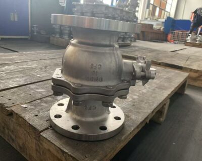
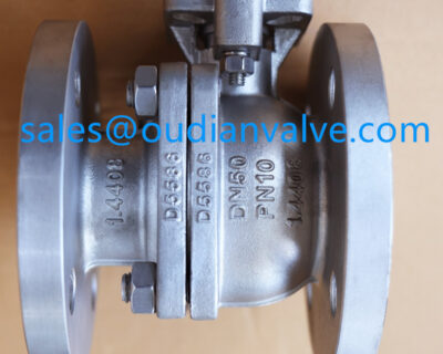
A two-piece body divides into a primary body and an end connection piece joined by external bolting or threaded connections. This setup allows valve teardown for seal and seat replacement, though the valve must be removed from the pipeline before maintenance can proceed. Two-piece valves balance initial fabrication cost against field reparability, making them common in general industrial processing lines.
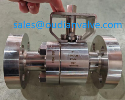
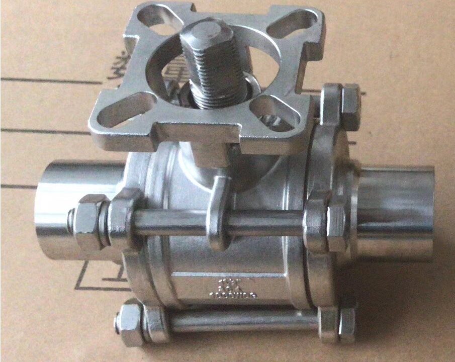
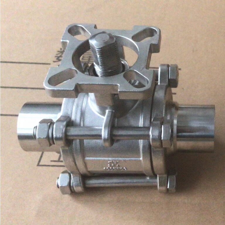
A three-piece body contains a central body section sandwiched between two independent pipe-end connectors held together by external tie rods. Field technicians can swing out the central body housing by loosening the outer bolts while leaving the pipe ends welded or threaded in position. This inline servicing feature makes three-piece valves preferred in pharmaceutical, food processing, and chemical facilities where frequent sanitation and seal maintenance occur.
One-Piece Body
A solid cast body provides exceptional structural strength and minimizes external joint leak paths. Internal components cannot undergo field servicing, making the valve disposable upon seat wear.
Two-Piece Body
Divided housing enables complete internal inspection and seat replacement during scheduled plant turnarounds. The unit requires complete unbolting from the pipeline before maintenance can begin.
Three-Piece Body
Central section swings out between pipe flanges for inline seat and seal replacement. Ideal for welded piping installations where cutting pipe to service valves is impractical.
Top-Entry and Side-Entry Valve Architectures
The entry configuration determines how internal components enter the valve body during fabrication and how maintenance crews access internal trim during overhauls. Top-entry and side-entry designs offer distinct trade-offs between structural profile and servicing convenience.
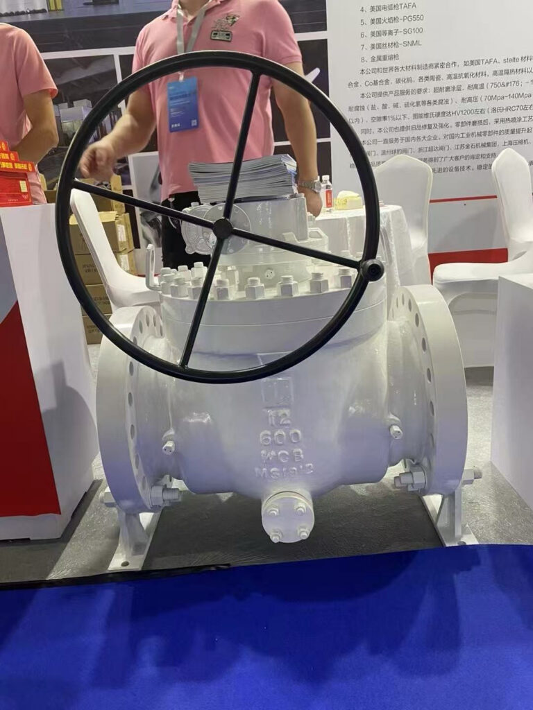
Top-entry ball valves feature a removable bonnet flange positioned directly over the ball chamber. Technicians remove the bonnet cover to lift out the ball, seats, and stem seals while the valve body remains fully welded into the pipeline. This top-down access proves critical in high-pressure steam distribution, nuclear power headers, and subsea tie-backs where cutting welded joints would introduce safety hazards and extended downtime.
Side-entry ball valves assemble through lateral body sections joined along one or two flanged or threaded planes. These valves represent the predominant industrial manufacturing approach due to simpler casting methods and reduced material thickness. While side-entry models cost less to manufacture, internal servicing requires removing the entire valve assembly from the piping run to separate the body segments.
| Característica | Top-Entry Style | Side-Entry Style | Operational Trade-Off |
| Acceso de mantenimiento | Inline Bonnet | Line Removal | Top-entry allows fast inline repairs without cutting welded joints. |
| Casting Complexity | Higher Mass | Standard Machining | Side-entry models feature lighter body castings and lower procurement costs. |
| Joint Leak Paths | Single Bonnet | Flanged Halves | Fewer body joints in top-entry reduce fugitive emission leak points. |
| Structural Rigidity | Monolithic Shell | Bolted Halves | One-piece top-entry bodies resist bending loads from heavy piping runs. |
Material Compatibility and Seat Sealing Options
Selecting durable valve materials preserves process containment across wide temperature spans, corrosive chemical streams, and abrasive particulate loads. Metallurgy and polymer formulations must match the specific chemical behavior of the process fluid.
Valve body housings frequently use cast or forged carbon steel for non-corrosive hydrocarbons and general industrial steam services. Stainless steel varieties provide corrosion resistance against aggressive chemical solutions, clean steam, and marine environments. For commercial water treatment, agricultural irrigation, and mild acid distribution, rigid PVC ball valve construction offers lightweight handling and resistance to galvanic degradation.
Seat materials define the pressure and temperature boundaries of internal shutoff performance. Soft seats made from fluoropolymer compounds deliver tight bubble-tight shutoff under ambient to moderate thermal conditions. Metal-to-metal seating uses hardened alloys or thermal spray coatings to resist extreme heat, abrasive slurries, and high-velocity steam where polymer materials melt or scour.
- Stainless steel construction resists pitting and stress cracking in aggressive industrial and marine environments.
- Carbon steel housings provide high tensile strength and pressure containment for oil, gas, and structural utility lines.
- Thermoplastic PVC ball valves provide chemical inertness in low-temperature chemical dosing and plumbing systems.
- Soft polymer seat inserts seal tightly against the polished ball surface for zero-leakage gaseous containment.
- Hard-faced metal seats withstand abrasive slurry movement, soot blowing, and extreme thermal conditions without galling.

Actuation and Flow Control Integration
Quarter-turn ball valves interface directly with diverse actuation systems to provide remote flow control, plant safety trips, and automated batching. The mechanical torque required to pivot the ball governs actuator sizing and cycling speed.
Manual levers and handwheel gearboxes handle simple manual isolation where cycling happens infrequently. Operators rotate the lever ninety degrees to stroke the valve, with lever position indicating whether the port is open or closed. Gearbox operators reduce the physical effort needed to pivot large or high-pressure valves, allowing smooth manual operation without fluid hammering.
Pneumatic actuators use plant compressed air to drive rack-and-pinion or scotch-yoke mechanisms, providing fast shutoff speeds suitable for emergency isolation loops. Electric actuators deliver precise motor-driven rotation for remote locations where compressed air lines are absent. Although standard ball valves serve primarily as on-off isolation hardware, modified balls with V-notch or characterized contours provide responsive throttling control across intermediate flow rates.
Sizing an actuator with adequate safety margin accounts for increased breakaway torque caused by static friction, viscous process media, or prolonged periods between valve cycles.
Selecting the Right Ball Valve Type for Process Systems
System designers must balance hydraulic demands, operating temperatures, structural safety limits, and life-cycle maintenance costs when specifying ball valves. A systematic assessment prevents premature component failure and unnecessary capital expenditure.
Begin by evaluating process operating pressure and line diameter. Compact lines operating at moderate pressures function reliably with floating ball valves, whereas high-pressure lines and large diameters demand trunnion-mounted anchoring to control breakaway torque. Next, assess whether downstream pressure drop impacts pump efficiency; full-port valves preserve flow velocity, while reduced-port designs cut weight and cost where head loss is negligible.
Examine the installation method and maintenance accessibility before finalizing body geometry. Welded pipelines benefit from three-piece or top-entry bodies that allow internal trim replacement without pipe removal, whereas flanged utility headers pair well with economical two-piece models. Finally, verify chemical compatibility between internal elastomers, seat materials, and line media to avoid swelling, embrittlement, or seal failure.
Never install standard soft-seated floating ball valves in severe throttling services, as partially open operation exposes the exposed polymer seat faces to localized high-velocity erosion.
Frequently Asked Questions About Ball Valve Types
What distinguishes a floating ball valve from a trunnion-mounted ball valve?
A floating ball valve relies on upstream line pressure pushing an unanchored ball against the downstream seat to seal. A trunnion-mounted valve fixes the ball between mechanical shafts and utilizes spring-loaded seats to achieve positive isolation under high operational pressures.
When should a full-port ball valve be selected over a reduced-port model?
A full-port ball valve is needed when pipelines require mechanical pigging, slurry handling, or minimal head loss to preserve pumping efficiency. Reduced-port valves suit standard liquid and gas handling where modest pressure drop across the body does not impact system performance.
Why are three-piece ball valves preferred in sanitary processing systems?
Three-piece ball valves permit technicians to swing out the center body section for seal replacement and cleaning while the end connections remain connected to the line. This feature avoids cutting or unthreading welded piping connections during regular maintenance cycles.
Can standard ball valves be used for continuous flow throttling?
Standard round-bore ball valves perform poorly in sustained throttling because high-velocity flow erodes the exposed edges of soft polymer seats. Characterized V-port ball valves with hardened metal seating should be selected when proportional flow modulation is required.
What causes premature seat failure in industrial ball valves?
Premature seat deterioration results from chemical incompatibility with process fluids, operating beyond rated thermal boundaries, or particulate abrasion. Entrapped cavity fluid expanding under extreme temperature shifts can also distort seats unless appropriate body cavity relief mechanisms are present.
Summary of Ball Valve Selection
Matching the correct ball valve type to piping conditions preserves flow efficiency, lowers actuation requirements, and maintains long-term seal reliability. Evaluating operating pressure, fluid properties, maintenance access, and port sizing guides engineers toward durable valve performance. Careful review of manufacturer technical sheets before installation helps keep piping infrastructure safe and dependable throughout its service life.