


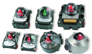
How Does a Proximity Switch Work?
The operational success of a non-contact sensor depends on matching the sensing physical principle with the composition of the target material and environmental conditions. Metal components, dense non-metallic solids, clear liquids, and bulk granular materials each interact differently with distinct sensing technologies. Selecting the correct switch configuration helps maintain dependable automated processes across rigorous industrial settings.

What Is a Proximity Switch and How Does It Function?
A proximity switch is an electronic sensor designed to replace conventional mechanical limit switches in industrial automation systems. Rather than relying on a physical arm, roller, or lever that must be depressed by a moving part, the switch emits a concentrated sensing field from its face. When an object approaches within a predefined distance, internal circuitry senses the disturbance and either closes or opens an electrical circuit.
Conventional mechanical switches experience mechanical fatigue, contact bounce, and physical degradation from repeated impacts. By eliminating moving elements, proximity switches prevent mechanical wear and maintain rapid switching frequencies over prolonged operational periods. The absence of moving components also leads to silent operation, making them practical across environments where mechanical clatter must be reduced.
Conventional Mechanical Switches
- Requires direct physical force from moving machinery
- Subject to mechanical contact bounce and physical fatigue
- Prone to seal degradation and ingress from particulate matter
- Produces acoustic noise during continuous rapid actuation
Solid-State Proximity Switches
- Operates entirely without physical contact with the target
- Eliminates mechanical wear on internal electrical contacts
- Features sealed housings suited for wet and dusty environments
- Delivers silent, high-frequency switching performance
Because there is no physical resistance against moving machine elements, proximity switches introduce no drag or mechanical obstruction to delicate products. This capability proves essential in high-speed bottling, automated packaging, and sensitive pharmaceutical assembly lines where direct physical impact could misalign or damage items.

Solid-state proximity switches monitor automated components without introducing mechanical drag or wear.
Operating Principles Across Different Sensor Types
Proximity switches fall into several primary categories based on the specific physical principle used to generate the sensing field. Inductive, capacitive, photoelectric, and ultrasonic designs each exhibit distinct strengths regarding target composition and sensing distances. Selecting the correct technology requires understanding how different target materials alter specific electrical and acoustic signals.
Inductive switches utilise inductive coupling to monitor conductive targets. An internal oscillator drives a coil that emits a high-frequency electromagnetic field from the front face. When a metallic target enters this field, circulating eddy currents form within the metal, drawing energy from the oscillator and attenuating its amplitude, which prompts the detector circuit to change output state.
Capacitive proximity switches function via electrostatic fields rather than magnetic fields. The sensing face contains two conductive plates configured as an open capacitor, generating an electrostatic boundary. As any target material with a dielectric constant greater than air enters the field, total capacitance increases, driving an internal oscillator to produce a switching signal for non-metallic solids, liquids, or metals alike.
| Sensor Technology | Operating Field | Target Compatibility | Operational Focus |
| Inductive | Electromagnetic | Conductive metals | Ferrous and non-ferrous metal positioning |
| Capacitive | Electrostatic | Liquids and solids | Sight glass monitoring and container level sensing |
| Photoelectric | Optical beam | Opaque and reflective | Long-range item tracking along conveyor belts |
| Ultrasonic | Acoustic waves | Universal surfaces | Clear container detection and bulk solids measurement |
Photoelectric proximity switches use an emitter to project light beams toward a target and a photodetector to capture reflections or interruptions. Ultrasonic proximity switches emit pulsed high-frequency sound waves and measure the acoustic echo returning from the target surface. Because ultrasonic units rely on sound reflection rather than optical characteristics, they detect transparent glass, clear plastics, and turbulent liquid surfaces without optical interference.
Electrical Configurations and Output Signals
The electrical interface of a proximity switch determines how it integrates with programmable logic controllers and automation relays. Switches are categorised by their unactuated state into normally open or normally closed configurations. A normally open switch prevents electrical current from flowing until a target enters the sensing field, whereas a normally closed switch allows current to pass continuously until a target appears.
Solid-state switching outputs are available in both direct current and alternating current variants. Direct current models typically employ transistor outputs configured as either positive-switching PNP or negative-switching NPN architectures. Choosing between PNP and NPN configurations depends on whether the host control system expects a current-sourcing or current-sinking input signal to register logic high.
System designers select normally open switches for standard component arrival detection and normally closed switches for fail-safe monitoring circuits. A normally closed loop registers an alarm state if an interconnecting cable becomes severed, supporting supervisory safety integrity.
Many modern industrial sensors provide complementary outputs featuring both normally open and normally closed poles within a single housing. This dual-output configuration allows one channel to confirm object presence while the second channel alerts the control system to wire continuity. The solid-state electronics inside the housing switch almost instantaneously, supporting rapid operational cycles without mechanical contact bounce.

Matching switch output logic to programmable logic controller inputs prevents signal integration errors.
Advantages and Limitations in Industrial Applications
Non-contact proximity switches provide distinct operational advantages over physical mechanisms, yet they also introduce specific operating limitations. The complete absence of mechanical contact eliminates physical friction, extending the operating lifespan of the device across demanding production schedules. Sealed solid-state enclosures also allow switches to perform reliably despite airborne dust, humidity, and lubricant splashing.
Conversely, proximity switches feature limited sensing ranges compared to visual cameras or long-range radar devices. Inductive and capacitive units require targets to pass within close proximity of the sensor face, necessitating rigid mounting brackets that resist vibration. Environmental build-up on the sensing face can also alter detection thresholds if left unaddressed.
Ventajas
- Extended service life resulting from zero mechanical wear and friction
- Robust sealed housings that tolerate moisture, dust, and temperature variations
- High-speed electrical switching suitable for rapid automated packaging cycles
- Silent operation without the acoustic impact noise of mechanical levers
Limitaciones
- Restricted detection range requiring close proximity to passing targets
- Potential false triggering from metal swarf or thick surface build-up
- Material-dependent detection ranges requiring calibration for non-ferrous metals
Recognising these constraints allows automated systems to position sensors where target paths remain predictable and repeatable. Pairing robust housing materials with appropriate sensing technologies helps maintain operational continuity across demanding manufacturing operations.
Key Factors When Selecting a Proximity Switch
Specifying the correct proximity switch requires evaluating target characteristics, ambient environmental conditions, and mechanical constraints. The composition of the target dictates whether an inductive, capacitive, optical, or ultrasonic sensing principle is necessary. Metal targets operate efficiently with inductive models, whereas non-metallic packaging, liquids, and bulk grains require capacitive or acoustic solutions.
The available detection range determines where the switch can be installed relative to moving machine parts. Inductive sensors feature reduced correction factors when detecting non-ferrous metals such as aluminium, copper, or brass compared to standard mild steel. Designers must account for this reduction in sensing distance to avoid mechanical collisions between the switch face and high-speed machinery.
- Target material composition and surface reflectivity properties
- Required detection distance between the sensor face and the passing component
- Ambient operating temperatures, washdown chemicals, and airborne moisture
- Mounting style constraints, such as flush or non-flush installation in metal tooling
- Electrical supply compatibility and required control logic architecture
Mounting styles also dictate sensor performance near surrounding metal structures. Flush-mounted sensors feature internal radial shielding that prevents side-sensing, allowing them to sit recessed within metal tooling. Non-flush models project an unshielded field that extends laterally, offering longer sensing ranges but requiring open clearance around the circumference of the sensing barrel.

Flush mounting allows proximity switches to sit securely within metal machine tooling without false triggering.
Installation Practices and Safe Disconnection
Correct mechanical installation preserves switch performance and protects the sensing face from catastrophic mechanical impact. Brackets must be rigid enough to withstand machinery vibration without shifting alignment over extended operating cycles. Furthermore, wiring runs must be routed away from high-voltage motor cables to reduce the risk of electromagnetic interference corrupting delicate switching signals.
When maintenance, recalibration, or machine retooling requires isolating an active sensor, technicians must follow a structured shutdown procedure. Removing or servicing an electrically live switch can cause short circuits or unintended machine movement. A three-step electrical isolation procedure helps support personal safety and equipment integrity during maintenance.
Always isolate the circuit breaker or power supply before disconnecting sensor wiring. Never pull directly on the flexible cable sheath, as internal conductors can separate and cause intermittent connection faults.
- Identify the dedicated power source supplying the proximity switch, such as an external power supply or machinery distribution block.
- Disconnect the electrical supply by opening the circuit isolator, switching off the supply breaker, or unplugging the keyed quick-disconnect cable.
- Confirm the switch-off state by checking the integrated diagnostic light emitting diode on the sensor barrel to verify no electrical power remains.
Once power is completely removed, technicians can safely clean the mounting threads, inspect the sensing face, or replace the unit. Verifying the absence of voltage with a calibrated meter provides an extra level of safety before handling exposed terminals.
Routine Maintenance and Troubleshooting Procedures
Proximity switches require minimal maintenance due to their solid-state construction, but adverse operating conditions can still cause unexpected faults. When a sensor fails to register a target or remains locked in an energized state, systematic troubleshooting resolves the issue quickly. Technicians should evaluate primary electrical supplies, physical alignment, and environmental factors in sequence.
Contamination on the sensing face is a frequent cause of erratic switching behaviour. In capacitive systems, moisture films or powder residues alter the electrostatic boundary, simulating a continuous target presence. For inductive switches, accumulating metallic swarf or machining shavings can hold the internal oscillator in a damped state, causing the output to remain locked on.
Power Verification
Inspect the incoming supply voltage at the sensor terminals to confirm it meets operating specifications under full load conditions.
Face Cleaning
Wipe the sensing face clean of oil films, conductive dust, metal shavings, and chemical scale using an approved non-abrasive solvent.
Mechanical Alignment
Confirm that vibration has not shifted the mounting bracket or pushed the target beyond the nominal operating distance of the switch.
If the device remains unresponsive after cleaning and alignment, check the switching output with a multimeter while manually introducing a target. A persistent lack of output response indicates internal circuit damage, likely caused by voltage spikes or direct physical impact. Replacing damaged units promptly restores automation timing and protects downstream equipment.

Regular inspection of sensor faces and mounting brackets prevents unexpected production line stoppages.
Industrial Applications and Future Technological Trends
Proximity switches operate across virtually every sector of modern automated manufacturing. In brewing, dairy processing, and food production, sealed stainless steel capacitive and photoelectric switches verify bottle filling, cap placement, and hygienic valve positions. In heavy manufacturing, mining, and metal fabrication, robust inductive sensors monitor hydraulic cylinder strokes and crane hoist boundaries under extreme mechanical stress.
Technological advancements continue to expand the intelligence and diagnostic capabilities of solid-state sensors. Digital communication protocols such as IO-Link allow proximity switches to transmit real-time diagnostic telemetry, internal temperature values, and target proximity metrics to supervisory control networks. This continuous data stream enables predictive maintenance algorithms to detect failing components before unexpected breakdowns occur.
Hygienic Process Industries
High-grade stainless steel housings resist intensive washdown chemicals and thermal cycling in pharmaceutical, dairy, and beverage production environments.
Predictive Maintenance Systems
Smart sensors feed continuous signal strength data into industrial networks, allowing maintenance teams to identify mechanical misalignments early.
The integration of machine learning algorithms with smart sensors allows automated facilities to analyse minor signal fluctuations over time. Detecting subtle shifts in target distance or vibration profiles enables scheduled adjustments during routine downtime. As industrial automation advances, proximity switches will remain indispensable silent facilitators of modern manufacturing efficiency.
Frequently Asked Questions About Proximity Switches
What is the main difference between inductive and capacitive switches?
Inductive proximity switches detect only metallic targets by generating an electromagnetic field that forms eddy currents in conductive metals. Capacitive proximity switches generate an electrostatic field, allowing them to sense both metallic and non-metallic materials, including plastics, glass, paper, and liquids.
What does normally open mean on a proximity switch?
A normally open configuration keeps the electrical circuit disconnected while no target is present in the sensing zone. When an object enters the detection field, the internal solid-state switch closes the circuit and permits electrical current to flow to the connected control system.
How do environmental conditions affect proximity sensors?
Extreme temperature fluctuations can alter sensing distances slightly, while moisture, dust, or metal shavings accumulating on the sensing face may trigger false switching signals. Selecting rugged housings with suitable ingress protection ratings helps maintain reliable performance in challenging environments.
Can proximity switches detect liquids?
Capacitive, photoelectric, and ultrasonic proximity switches can detect liquids across a variety of industrial applications. Capacitive models can even sense aqueous liquids through non-metallic container walls, such as plastic sight tubes or glass bottles, by registering changes in dielectric capacitance.
What causes a proximity switch to stop detecting?
Common causes include interrupted power supply voltages, mechanical misalignment caused by vibration, accumulated debris on the sensing face, or targets passing beyond the calibrated detection range. In severe cases, high-voltage electrical transients or physical impacts may cause internal electronic failure requiring sensor replacement.
Selecting and Operating Proximity Switches
Proximity switches deliver fast, dependable, non-contact detection across modern industrial automation by translating physical field disturbances into clear switching signals. Matching the correct sensing technology to target materials, maintaining rigid mechanical mounting, and performing routine surface cleaning supports reliable machinery operation. Careful attention to wiring configurations and safety practices preserves system efficiency throughout the operating life of the equipment.