


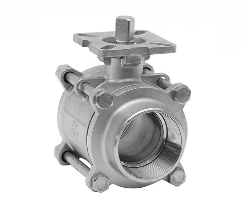
Valve End Connection Types, Screwed, Flanged, Welded
Valve End Connection Types, Screwed, Flanged, Welded
Valve end connection types determine how a valve body physically joins adjacent pipework, directly dictating mechanical strength, containment reliability, and servicing access throughout the lifespan of an installation. The three primary configurations used across industrial fluid networks are screwed, flanged, and welded connections. Screwed connections provide a compact method for smaller line sizes, flanged designs allow modular installation and straightforward disassembly across broad pressure ranges, and welded joints establish permanent, high-integrity joints for severe operating environments.
Selecting an appropriate connection requires evaluating system operating pressure, line temperature, fluid chemistry, and expected maintenance frequencies. Improper selection introduces structural vulnerabilities, accelerates leakage risks, or creates prohibitive disassembly hurdles during planned plant turnarounds. Matching the mechanical traits of the valve boundary to specific process conditions maintains pipeline stability and long-term operating containment.
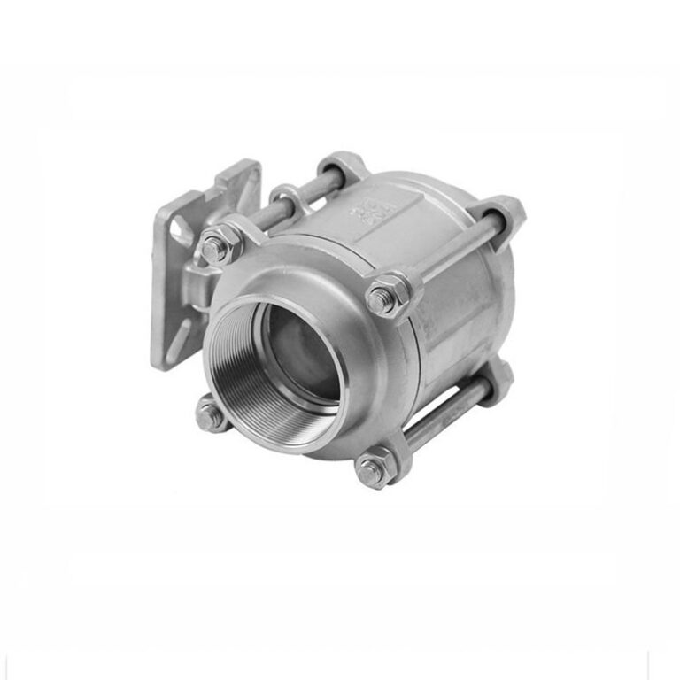
Screwed End Connections and Mechanical Design
Screwed end connections attach valves to piping by engaging machined male and female threads directly on the component interfaces. This design is widely deployed on compact valve bodies and lower-volume lines where rapid mechanical assembly without specialized fabrication tools is beneficial.
The threads on screwed valves are manufactured with either straight or tapered profiles designed to mate with matching pipe threads. Straight threads serve primarily to pull the joint together mechanically, relying on compression washers, O-rings, or secondary gaskets to block fluid pathways. Tapered pipe threads, by contrast, create mechanical interference as the mating flanks deform against each other during makeup, establishing a progressive friction lock along the spiral path.
Because spiral thread roots inherently form micro-clearances that can become potential fluid paths, threaded joints require supplemental sealing agents during assembly. Liquid thread sealants, PTFE sealing tapes, or specialized packing cords fill the minute gaps between the machined peaks and roots to prevent fluid migration. In systems where the valve body material is weldable but experiences extreme operating temperature swings or mismatched thermal expansion coefficients, thread joints can be seal-welded—often termed honey sealing—around the perimeter to protect the mechanical thread interface against operational shifting.
Threaded connections rely on precise machining and thread engagement depth to maintain structural hold, while sealants or seal welding prevent spiral leakage through micro-gaps.
Machined threads provide direct mechanical engagement on compact pipeline assemblies.
Trade-Offs and Leak Resistance of Screwed Ends
Screwed end valves offer clear economic and spatial advantages, but mechanical limitations restrict their implementation in larger pipeline systems or critical chemical processes. Understanding these functional boundaries prevents premature mechanical failure and unexpected fluid loss.
Threaded assemblies excel in low-footprint installations where lightweight components and fast installation cycles are mandatory. The absence of heavy flanges, loose bolting hardware, or specialized welding rigs lowers upfront component costs and speeds up fabrication in utility, air, and low-pressure water systems. Because no hot work permits are needed during initial assembly, threaded lines can be erected safely in areas containing flammable atmospheres or delicate surrounding instrumentation.
The mechanical rigidity of threaded joints decreases sharply as nominal line sizes increase beyond standard thresholds. Valves with nominal diameters exceeding 50 mm present major installation hurdles, as the torque required to tighten the mating components without galling or cross-threading becomes difficult to achieve in the field. Furthermore, cyclical thermal expansion, piping vibration, and external bending moments can loosen threaded engagements over time, opening microscopic leakage channels that require thread re-tightening or replacement of the joint.
Ventajas
- Low initial valve procurement and fitting costs
- Compact physical envelope suitable for congested skid packages
- Simple assembly requiring standard pipe wrenches without hot work
Limitaciones
- Practical size threshold limited to nominal sizes of 50 mm or less
- Vulnerable to loosening under heavy vibration or cyclical thermal loads
- Spiral clearance paths present potential leak channels under elevated pressure
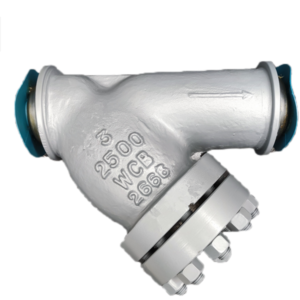
Threaded connections remain common in utility water and compressed air lines.
Installation and Maintenance for Threaded Piping Systems
Installing screwed valves requires careful alignment to avoid cross-threading, galling, or over-torquing the valve body casting. Applying excessive rotational force can distort internal valve seating surfaces, leading to internal through-leakage long before the joint is brought into service.
To facilitate routine removal and inspection of screwed valves without dismantling entire pipeline runs, engineers integrate pipe unions or companion fittings at strategic positions. Valves with nominal sizes up to 50 mm may also be fitted with a sleeve, where the internal or external thread holds the two parts together securely while permitting controlled uncoupling. Without union connections or threaded sleeves, unscrewing a valve from rigid, fixed piping requires cutting the line or backing out extensive upstream spools.
Routine maintenance protocols for threaded systems prioritize external inspection for crusting, weepage, and atmospheric corrosion along the thread roots. Because exposed male threads are thinner than the pipe wall, they are susceptible to stress concentration and localized external corrosion. When a leak appears at a threaded joint, simply tightening the fitting under pressure is risky; depressurizing the line, backing off the connection, and renewing the sealing compound represents standard engineering practice.
- Inspect thread profiles for burrs, flattened crests, or foreign grit before thread makeup.
- Apply approved thread sealant or PTFE tape evenly across male threads, avoiding the lead thread to protect valve internals.
- Incorporate pipe unions or threaded sleeves adjacent to the valve to streamline future component replacement.
- Avoid over-tightening beyond recommended engagement depths to prevent cracking cast valve bodies.

Integrating pipe unions adjacent to screwed valves enables straightforward component removal.
Flanged End Connections and Gasket Mechanics
Flanged end connections represent the most commonly used valve end configuration in commercial and heavy industrial processing systems. This method relies on bolted mechanical joints that compress a stationary gasket between two matching flange rings to establish an external pressure boundary.
A flanged valve features integral flanges cast or forged onto both end ports, containing standardized bolt holes that align with matching pipe flanges. During assembly, the valve drops between the mating pipe flanges, a gasket of selected metallurgy and filler is centered between the faces, and studs or bolts are tensioned across the circumference. The compressive load applied by the bolting deforms the gasket material into the microscopic surface grooves of the flange faces, creating an impervious seal against the flowing medium.
Different flange face configurations optimize gasket loading for specific operating regimes. Raised face flanges concentrate bolt preload onto a defined surface area, maximizing gasket seating stress without requiring extreme bolt torque. Flat face flanges provide uniform support across the entire contact diameter, commonly used with brittle iron valve bodies to avoid bending stresses. Ring type joint flanges utilize precision-machined metallic rings set into matching circular grooves, delivering outstanding resistance against pressure extrusion in severe service applications.
Raised Face
Concentrates bolt tension over a elevated circular area to maximize gasket seating stress.
Flat Face
Distributes load across the entire surface to eliminate bending moments on cast iron bodies.
Ring Type Joint
Compresses a solid metallic ring into precision grooves for critical high-pressure lines.
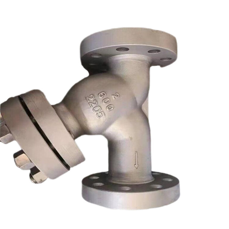
Bolted flange joints allow convenient valve removal without altering adjacent pipework.
Pressure and Temperature Limits of Flange Joints
Flanged connections accommodate almost all pipe sizes and broad pressure ranges, making them exceptionally versatile across industrial infrastructure. Their primary operational benefit lies in ease of installation and disassembly, allowing valves to be removed for overhaul or testing simply by unbolting the studs.
Despite their widespread utility, flanged assemblies carry notable physical and thermal limitations compared to welded designs. Flanged valves are inherently heavier and more expensive to manufacture than threaded or welded equivalents due to the additional metal required for flange rings, companion flanges, gaskets, and heavy stud sets. In elevated structural racks, the combined weight of multiple flanged valves demands substantial pipe hangers and support engineering.
Thermal stability introduces another critical constraint for flanged connections. When operating temperatures exceed 350 degrees, the physical behavior of the joint changes significantly as bolts, gaskets, and flange rings undergo thermal expansion and metallurgical relaxation. Under sustained elevated temperatures, bolting creep can cause fasteners to slacken, reducing the active compressive load on the gasket. Under high pipe stresses and thermal cycling, this loss of bolt tension allows process fluid to bypass the gasket, causing joint leakage.
When system temperatures exceed 350 degrees, bolt relaxation and gasket softening reduce compressive load, increasing the probability of flange leakage under high thermal stress.
Elevated temperature piping requires careful monitoring of bolt tension and gasket integrity.
Welded End Connections and Joint Geometry
Welded end connections fuse the valve body directly to the adjoining pipework through metallurgical bonding, creating a continuous pressure envelope without mechanical seams or elastomeric seals. This design delivers exceptional mechanical strength and zero-leakage containment under demanding operating loads.
Welded valves fall into two distinct structural categories based on pipe size and joint geometry: socket weld ends and butt weld ends. Socket weld connections feature a recessed bore at each valve port that receives the square-cut end of the pipe. A fillet weld is deposited around the external circumference of the valve socket shoulder, securing the pipe mechanically. Socket welding is commonly utilized on smaller lines, typically below 50 mm nominal diameter, where rapid fit-up and direct alignment are advantageous.
Butt weld connections are designed for larger nominal diameters and severe service duties. The valve ends are machined with precision weld bevels, typically matching the schedule, wall thickness, and bevel geometry of the mating pipe. The valve is aligned with the pipe ends, spaced with a defined root gap, and fused through full-penetration multi-pass welding. This approach creates a smooth, continuous interior bore that minimizes turbulent fluid drag while matching the mechanical yield strength of the parent pipe.
Socket Weld Ends
- Recessed socket accepts plain-end pipe for rapid alignment
- Utilizes external fillet welds around the joint shoulder
- Applied predominantly to nominal sizes below 50 mm
- Forms an internal expansion gap susceptible to crevice attack
Butt Weld Ends
- Beveled ends match pipe schedule and wall thickness
- Utilizes full-penetration circumferential groove welds
- Standard configuration for large-bore, severe-service piping
- Maintains a continuous internal bore profile without crevices
Machined beveled ends allow full-penetration welding directly to adjoining pipework.
Performance of Welded Joints in Severe Service
Welded end connections provide maximum leak tightness and structural robustness across all pressure and temperature classifications. In systems subjected to intense pressure surges, thermal cycling, or high mechanical bending loads, welded joints offer far greater containment reliability than bolted flanged connections.
Because welded joints form a monolithic metal boundary, they are the preferred choice for hazardous, toxic, or volatile media where external fugitive emissions are unacceptable. Major applications include thermal power stations, nuclear energy projects, ethylene facilities, and high-pressure steam distribution headers. In these environments, eliminating mechanical gaskets removes the danger of gasket blowout or thermal relaxation under fluctuating load conditions.
However, welded valves require specific engineering safeguards and fabrication controls. In socket weld joints on lines below 50 mm, an intentional clearance gap exists between the bottom of the socket and the pipe end to accommodate thermal expansion during welding. Corrosive media can concentrate within this internal recess, accelerating localized crevice corrosion. Furthermore, severe piping vibration can cause fatigue cracking at the root of the fillet weld, restricting socket weld usage in cyclical or highly corrosive operations.
Large-bore butt welded valves require rigorous edge preparation, root pass inspection, and certified welders to achieve defect-free joints capable of withstanding extreme thermal loads.

Skilled welding execution preserves parent metal properties and joint containment integrity.
Evaluating Valve End Connection Types for Piping Design
Selecting the optimal valve connection requires balancing process safety, structural loads, lifecycle economics, and maintenance strategy. Evaluating key operating criteria systematically prevents costly redesigns or premature piping failures during plant operation.
System operating conditions dictate the baseline mechanical boundaries for connection selection. Where temperatures exceed 350 degrees or pressures push into critical classes, welded ends provide superior resistance to thermal relaxation and joint weeping. In moderate utility services operating under ambient temperatures, threaded or flanged connections provide dependable containment at lower capital and installation costs.
Maintenance philosophy and space constraints form the second critical evaluation layer. Facilities requiring frequent valve removal for cleaning, recalibration, or statutory inspection benefit from flanged connections, despite their higher weight and bulk. Conversely, systems intended for long-term reliable operation without component disassembly favor welded construction. For compact equipment skids and nominal lines of 50 mm or less, screwed connections minimize weight and spatial footprint while keeping fabrication straightforward.
- Determine design pressure and maximum operating temperature to identify metallurgical and gasket limits.
- Assess fluid toxicity, flammability, and environmental containment requirements to evaluate zero-leakage priorities.
- Establish required maintenance frequencies and whether in-line servicing or shop overhaul is planned.
- Review piping layout constraints, total weight allowances, and spatial clearance for bolt removal or tool access.
- Factor in local fabrication capabilities, including welder certification requirements and non-destructive examination availability.
Engineering design reviews balance operational safety, maintenance frequency, and installed weight.
Technical Comparison of Screwed, Flanged, and Welded Ends
A structured comparison highlights the operational trade-offs between screwed, flanged, and welded valve end connections. Each design configuration balances mechanical integrity, spatial footprint, procurement cost, and maintenance accessibility differently.
The comparative matrix below outlines performance characteristics across key engineering parameters, summarizing how mechanical features influence installation decisions across industrial fluid systems.
| Tipo de conexión | Rango de tallas | Disassembly Ease | Primary Application Focus |
| Screwed End | Up to 50 mm | Moderado | Compact utility piping and low-pressure skid systems |
| Flanged End | All sizes | Alto | Modular industrial processing requiring routine valve removal |
| Socket Weld | Below 50 mm | Bajo | High-pressure small-bore piping with minimal servicing needs |
| Butt Weld | All sizes | Muy bajo | Severe service power, nuclear, and ethylene distribution lines |
Reviewing these mechanical boundaries clarifies why single facilities often deploy all three connection styles simultaneously across different process subsystems. Matching connection attributes to localized line parameters creates balanced, cost-effective piping architecture.
Different connection geometries serve distinct structural and operational functions.
Frequently Asked Questions About Valve End Connections
Why are screwed end valves generally limited to sizes of 50 mm or smaller?
Screwed end valves are primarily limited to nominal diameters of 50 mm or less because larger pipe threads require excessive torque to tighten properly without galling or thread deformation. In larger sizes, achieving a dependable mechanical seal becomes difficult in field conditions, and the bulk of the piping makes rotating components impractical.
What causes flanged connections to develop leaks at temperatures exceeding 350 degrees?
At temperatures exceeding 350 degrees, bolting, gaskets, and flange rings undergo thermal expansion, stress relaxation, and material creep. As bolt preload drops under sustained heat, compressive stress on the gasket decreases significantly, allowing process fluids to escape under high piping stress.
What is honey sealing on a threaded valve joint?
Honey sealing refers to seal-welding the outer joint perimeter of a threaded connection after mechanical makeup. This practice is used when valve body materials are weldable but operate under wide temperature variations or mismatched thermal expansion rates, preventing fluid migration through thread clearances.
Why are socket weld connections restricted in certain corrosive environments?
Socket weld connections leave an internal mechanical expansion gap between the end of the pipe and the socket shoulder. Corrosive process media can stagnate within this crevice, causing localized crevice corrosion, while severe piping vibrations can cause fatigue failures at the fillet weld root.
When should butt weld connections be chosen over flanged connections?
Butt weld connections should be selected for severe service operations involving critical pressures, extreme temperatures, or hazardous fluids where zero external leakage is required. They eliminate bolted joints and gaskets, reducing weight and eliminating maintenance concerns associated with gasket failure in power, nuclear, and petrochemical facilities.
Selecting the Appropriate Valve End Connection
Choosing between screwed, flanged, and welded valve end connections requires aligning mechanical capabilities with process hazards, operating pressures, and maintenance accessibility. Screwed connections remain ideal for low-pressure lines up to 50 mm where compact installation is paramount, flanged connections offer modular flexibility and convenient disassembly across standard industrial processes, and welded ends provide structural reliability for high-temperature, severe-service piping systems.