


Valve Backseat Function and Engineering Standards
Defining the Valve Backseat Component
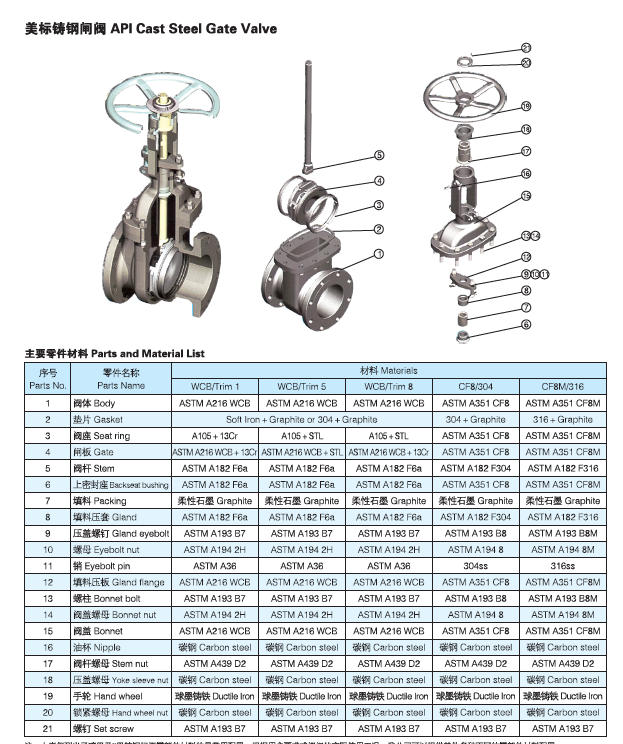
In industrial piping assemblies, a valve backseat is a designated mechanical contact surface manufactured into the valve trim. It consists of a precisely contoured shoulder or bevel on the valve stem that aligns with a corresponding stationary seat machined directly into the lower underside of the valve bonnet. Because it interacts directly with process fluid under specific operating configurations, engineering codes classify the backseat as a trim component subject to strict dimensional and metallurgical tolerances.
Manufacturers produce backseat contact faces from durable materials designed to resist galling, mechanical erosion, and chemical degradation. Common constructions incorporate hard-faced metal alloys, corrosion-resistant stainless grades, or resilient polymers matching the service class of the fluid. The structural strength of these materials preserves the profile of the seating surface across mechanical thermal cycles.
The backseat functions strictly as an emergency or secondary sealing interface, complementing the primary containment provided by the stuffing box.
Integrating a backseat feature into isolation equipment provides a mechanical stop that prevents the stem from being pushed out through the bonnet under extreme fluid force. This geometric limitation preserves internal component alignment and provides a secondary containment boundary whenever line pressure acts on the internal cavity.
How the Valve Backseat Works
Mechanical operation relies entirely on stem position and linear travel inside the valve body. Rotating the handwheel or energizing an actuator to lift the closure element raises the valve stem until its machined shoulder meets the bonnet seat face.
The machined shoulder on the stem creates a mechanical seal when brought into firm contact with the bonnet seat.
When the valve reaches the fully open position, mechanical thrust forces the mating angles together to establish a tight metal-to-metal or soft-seated boundary. This seal halts the migration of pressurized process liquid or gas into the upper bonnet neck.
- Actuation moves the stem upward, lifting the disc or wedge away from the primary flow passage.
- The upper stem collar makes positive physical contact with the bonnet mating surface at the end of the stroke.
- Thrust applied through the operating mechanism compresses the two surfaces together to isolate the stuffing box from line media.
With the backseat fully closed against the bonnet, line fluid remains confined within the pipeline waterway and lower body cavity. Fluid cannot travel upward to load the flexible packing rings, preventing premature deterioration caused by chemical contact or operational pressure swings.
Backseat Sealing Compared to Stem Packing
Fluid isolation along the stem relies on two distinct barriers designed for different operating demands. The stuffing box serves as the primary dynamic seal during everyday operations, while the backseat provides a static secondary seal available only at full stem extension.
| Sealing Component | Seal Category | Operational State | Primary Function |
| Stuffing Box Packing | Dynamic Seal | Continuous Service | Maintains stem containment during full stroke travel and cycling. |
| Backseat Interface | Static Seal | Fully Open Position | Isolates packing chamber from line media when fully retracted. |
| Body Cavity Relief | Cavity Boundary | Closed Position | Relieves line pressure exposure on packing when closure member seats. |
Flexible packing rings reside within the stuffing box, compressed around the smooth stem by a gland follower and gland bolts. These rings tolerate continuous axial movement during valve strokes, maintaining external fluid containment while the disc moves between open and closed positions.
By contrast, the backseat cannot provide sealing while the stem travels through intermediate positions. It establishes contact only when the valve fully opens, presenting an impermeable metal interface that stops fluid velocity and line pressure from continuously impinging against the softer packing set.
Valve Types Utilizing Backseat Trim
Industry standards specify backseat features primarily within multi-turn, linear isolation valves. Gate and globe configurations commonly feature this geometry due to their dedicated rising-stem architecture and heavy-duty process isolation roles.

Gate Valve Assemblies
Wedge and parallel slide gate valves incorporate backseats to protect stem packing during prolonged open run periods in crude oil, gas, and utility supply headers.

Globe Valve Assemblies
Globe valves use precision backseat collars to prevent process fluid from reaching packing components during sustained flow isolation and flow diversion service.
Quarter-turn valves such as standard ball, butterfly, and plug designs do not utilize backseat arrangements. Their rotating stems do not create the axial thrust needed to engage a mechanical shoulder against an upper bonnet recess.
Valve Backseat Test Procedures
Standardized workshop pressure testing verifies the structural soundness and tight shut-off capability of newly manufactured or reconditioned backseats. Technicians conduct this evaluation on a hydrostatic test rig before applying paint or protective exterior coatings.
Technicians secure the valve assembly on a certified test bench to monitor fluid retention at elevated test pressures.
API 598 section 6.2 outlines the formal procedure for inspecting backseat integrity during production quality acceptance. The inspection follows specific preparation, loading, and observation steps to confirm that fluid does not bypass the mating trim faces.
- Secure the valve assembly firmly on the test bench with the disc or wedge placed in the fully open position and both pipeline connection ends closed.
- Loosen the packing gland fasteners entirely so that the packing follower exerts no compressive load on the internal packing rings.
- Fill the valve body cavity with clean test water, vent trapped air, and elevate internal hydraulic pressure until reaching the mandated test level.
- Observe the packing chamber and stem exit point continuously for visible drops, moisture weeping, or pressure decay across the mandatory duration.
Backseat test pressure must not fall below 110% of the maximum allowable working pressure corresponding to the valve body material and class rating. For instance, a 20-inch 900 lb valve fabricated from ASTM A216 WCB cast carbon steel carries an ASME B16.34 design pressure of 2252 psi, requiring a backseat test pressure of 2477 psi.
Testing Standards and Duration Requirements
Different engineering codes govern holding periods and acceptable leakage tolerances during hydrostatic verification. Testing personnel must follow the specific timing parameters matching the design standard of the valve.
API 598 Standard Timing
For standard refinery and industrial valves, inspection durations run for 15 seconds on valve sizes less than 2 inches. Sizes greater than 2 inches require a continuous pressure hold of 60 seconds.
API 6D Pipeline Specifications
Pipeline valves inspected under API 6D section 10.2 require a 2-minute duration for sizes less than 4 inches. Valves greater than 6 inches require a 5-minute hold at 110% design pressure.
Acceptance criteria under both testing specifications require zero allowable leakage past the mating metal faces. Any visible water escaping through the uncompressed packing chamber constitutes a test failure that requires disassembly, machining adjustments, or component replacement.
Pressure gauges on the test manifold must remain steady without detectable needle drop while the packing gland remains loose. Verifying absolute shut-off under these factory conditions confirms the mechanical concentricity of the stem and bonnet trim.
Common Misconceptions and Operational Hazards
A frequent operational misunderstanding is that field personnel should actively backseat an operating valve to preserve packing ring life. Running a valve jammed tight against its backseat for extended periods introduces severe mechanical hazards that compromise equipment integrity.
Continuous backseat engagement during active process runs can cause severe mechanical jamming and packing blowouts when operating temperatures change.
Thermal differentials between the valve body, stem, and bonnet can lock the backseat if handwheels are left fully torqued open.
Thermal expansion occurs at differing rates across the body, bonnet, wedge, and stem when hot process fluid flows through the waterway. If a valve is torqued into its backseat while cold or during fluctuating flow, differential metal expansion can bind the stem tightly against the bonnet, making closing the valve extremely difficult.
Prolonged engagement also deprives the packing rings of process contact and lubrication. Without standard hydraulic seating support, packing material can dry out, harden, and score the stem surface during subsequent strokes, resulting in packing blowouts upon valve closure.
Safe Deployment and Actuator Adjustment
Safe operation requires that technicians treat the backseat as an emergency isolation aid rather than a substitute for routine packing maintenance. Best practice dictates avoiding backseat deployment except when absolutely necessary and after exhausting alternative field sealing options such as drilling and tapping.
Manual Handwheel Practice
- Open the handwheel until the stem reaches the top of its mechanical travel.
- Rotate the handwheel back one full turn away from the fully open position.
- Confirm the backseat is disengaged to prevent thermal binding.
Actuated Valve Setup
- Set open travel limit switches precisely according to manufacturer specifications.
- Prevent electric motor over-torque at the end of the opening stroke.
- Calibrate pneumatic stop bolts to avoid mechanical jamming against the bonnet.
Relevant engineering standards explicitly warn against using backseats for packing replacement on pressurized systems. API 600 section 5.8.9 states that a backseat arrangement is a standard requirement for gate and globe valves but does not imply a manufacturer recommendation for adding or replacing packing under line pressure.
Similarly, API 589 section 6.2.3 clarifies that successful completion of a factory backseat test must never be construed as a recommendation to repack pressurized equipment. Backseats should only isolate packing temporarily when gland leakage occurs and formal plant shutdown for valve maintenance will follow promptly.
Preguntas frecuentes
What is the primary purpose of a valve backseat?
A valve backseat provides a secondary static seal that isolates the stem packing chamber from line pressure when the valve is in the fully open position. It prevents process fluids from escaping past the stem and acts as a mechanical travel stop.
Can technicians repack a valve while it is under line pressure?
Repacking a valve under line pressure using only the backseat is unsafe and strongly discouraged by industry standards like API 600. Backseats should never serve to allow gland packing replacement if line fluids are hazardous or operate at elevated temperatures.
What hydrostatic test pressure is used during a backseat test?
Backseat test pressure must equal at least 110% of the maximum allowable design pressure of the valve body material. For an ASME B16.34 design pressure of 2252 psi, the required test pressure reaches 2477 psi.
Why must a handwheel be backed off one turn after opening?
Rotating the handwheel back one full turn from the fully open position disengages the backseat shoulder. This action prevents the stem from jamming inside the bonnet due to differential thermal expansion between metals.
Which valve types include a backseat design feature?
Linear rising-stem isolation valves, primarily gate valves and globe valves, feature backseats as standard trim components. Quarter-turn valves like ball and butterfly designs do not incorporate this mechanical arrangement.
What is the acceptable leakage rate during an API 598 backseat test?
Zero visible leakage is permissible during an API 598 backseat inspection. Technicians inspect the stem and loosened packing gland under pressure, and any observed drops or weeping constitute an immediate test failure.
Summary of Valve Backseat Reliability
Valve backseats serve as critical secondary barriers that support fluid isolation and protect stem packing when linear valves operate fully open. Operating personnel must respect thermal limitations, disengage the seat during routine service runs, and avoid repacking pressurized piping systems without proper safety isolations. Following standardized testing protocols and manufacturer travel adjustments maintains long-term valve mechanical integrity across industrial facilities.