


ISO 5211 Mounting Flange Dimensions: Complete Guide for Valve Actuators
Einführung
When selecting a pneumatic actuator, electric actuator, or gearbox for an industrial valve, the mounting interface is an important consideration. The actuator must fit the valve mounting flange correctly and transmit sufficient torque to operate the valve safely and reliably.
ISO 5211 is an international standard for part-turn actuator attachments used on industrial valves. It establishes standardized mounting interfaces to help ensure dimensional compatibility between valves and actuators.
ISO 5211 mounting flange dimensions are commonly used in applications involving butterfly valves, ball valves, plug valves, pneumatic actuators, electric actuators, and manual gearboxes.
This guide explains the main ISO 5211 flange types, their dimensional characteristics, how to read an ISO 5211 flange chart, and what engineers should check before selecting an actuator.
1. What Is ISO 5211?
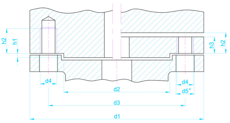
ISO 5211 specifies requirements for the attachment interfaces between industrial valves and part-turn actuators.
A part-turn actuator rotates the valve stem through a limited angle, commonly 90 degrees, to open or close a valve. Examples include pneumatic rack-and-pinion actuators, pneumatic scotch-yoke actuators, electric quarter-turn actuators, and manual worm gearboxes.
The standard helps define the mechanical interface between the valve and actuator, including mounting flange dimensions and drive arrangements.
Typical applications include:
- Butterfly valves
- Kugelhähne
- Plug valves
- Pneumatic actuators
- Electric actuators
- Manual worm gearboxes
- Automated process control systems
An ISO 5211 mounting interface can simplify actuator replacement, automation upgrades, and integration of valves and actuators from different manufacturers.
However, matching the flange designation alone does not guarantee that an actuator is suitable for a valve. Drive dimensions, torque requirements, mounting height, and operating conditions must also be checked.
2. Understanding ISO 5211 Flange Types
ISO 5211 mounting interfaces use designations such as F03, F04, F05, F07, F10, F12, F14, F16, F25, F30, F35, F40, F48, F60, F80, and F100.
The designation identifies a standardized interface configuration. It should not be interpreted as the valve nominal size or the actuator’s torque rating by itself.
For example, an F05 interface may be used with a suitable actuator and valve assembly, but the required drive geometry and torque capacity still need verification.
Common flange designations include:
| Flange type | Typical application context |
|---|---|
| F03 / F04 | Compact part-turn actuators and smaller valve assemblies |
| F05 / F07 | Small to medium actuator interfaces |
| F10 / F12 | Medium-sized actuator and valve assemblies |
| F14 / F16 | Larger actuator mounting interfaces |
| F25 / F30 | Larger industrial actuator assemblies |
| F35 and above | Larger mounting interfaces for demanding applications |
These are general application examples, not mandatory valve-size assignments. The correct flange type depends on the actuator design, valve mounting interface, and required operating torque.
3. ISO 5211 Mounting Flange Dimensions Chart
The following reference table summarizes key dimensions from the ISO 5211:2023 flange-dimension table. Dimensions are in millimetres.
| Flange type | d1 min. (mm) | d2 max. (mm) | d3 min. (mm) | Thread | h1 max. (mm) | h2 min. (mm) | h3 min. (mm) | No. of fasteners |
|---|---|---|---|---|---|---|---|---|
| F03 | 46 | 25 | 36 | M5 | 3 | 8 | 5 | 4 |
| F04 | 54 | 30 | 42 | M5 | 3 | 8 | 5 | 4 |
| F05 | 65 | 35 | 50 | M6 | 3 | 9 | 6 | 4 |
| F07 | 90 | 55 | 70 | M8 | 3 | 12 | 8 | 4 |
| F10 | 125 | 70 | 102 | M10 | 3 | 15 | 10 | 4 |
| F12 | 150 | 85 | 125 | M12 | 3 | 18 | 12 | 4 |
| F14 | 175 | 100 | 140 | M16 | 4 | 24 | 16 | 4 |
| F16 | 210 | 130 | 165 | M20 | 5 | 30 | 20 | 4 |
| F25 | 300 | 200 | 254 | M16 | 5 | 24 | 16 | 8 |
| F30 | 350 | 230 | 298 | M20 | 5 | 30 | 20 | 8 |
| F35 | 415 | 260 | 356 | M30 | 5 | 45 | 30 | 8 |
| F40 | 475 | 300 | 406 | M36 | 8 | 54 | 36 | 8 |
| F48 | 560 | 370 | 483 | M36 | 8 | 54 | 36 | 12 |
| F60 | 686 | 470 | 603 | M36 | 8 | 54 | 36 | 20 |
| F80 | 900 | 670 | 813 | M42 | 10 | 63 | 42 | 20 |
| F100 | 1,200 | 870 | 1,042 | M42 | 10 | 63 | 42 | 32 |
Important: The table is a reference for preliminary selection. Confirm the dimension definitions against the applicable edition of ISO 5211 and the actuator manufacturer’s drawing before manufacturing or ordering. Drive dimensions and any additional interface requirements must also be verified.
4. What Do the ISO 5211 Dimensions Mean?
Understanding the dimensional terminology helps engineers compare valve and actuator drawings.
4.1 Mounting Flange Dimensions
The mounting flange dimensions define the mechanical interface between the actuator and the valve.
They include flange geometry, the relevant diameters, and the dimensions needed for proper attachment. Both components must have compatible mounting interfaces.
4.2 Bolt Pattern and Thread Size
The bolt pattern determines the number and arrangement of the fasteners used to secure the actuator.
The thread specification identifies the nominal thread size used at the interface. The mating components must have compatible threaded or clearance-hole arrangements and sufficient fastener engagement.
4.3 Drive Interface
The actuator must transfer rotational torque to the valve stem or drive shaft.
Depending on the design, the drive may use a key, square drive, or another permitted configuration. The drive dimensions must match the valve stem or adapter.
An actuator with a matching mounting flange may still be incompatible if its drive geometry does not fit the valve.
4.4 Mounting Height and Clearance
The overall assembly must provide sufficient clearance between the valve, actuator, pipeline, and surrounding equipment.
Engineers should check the valve mounting height, stem extension, actuator envelope, adapter dimensions, and access required for installation and maintenance.
5. How to Select the Correct ISO 5211 Mounting Flange
Selecting an actuator mounting flange involves more than comparing two flange designations.
Step 1: Identify the Valve Type
Determine whether the valve is a butterfly valve, ball valve, plug valve, or another part-turn valve.
Different valve designs have different torque characteristics, stem geometries, and mounting arrangements.
Step 2: Confirm the Valve Mounting Interface
Obtain the valve manufacturer’s general arrangement drawing or mounting-interface drawing.
Confirm the flange type, bolt pattern, drive dimensions, and mounting height. Do not assume the interface based on the valve size alone.
Step 3: Calculate or Obtain the Required Torque
The actuator must provide sufficient torque throughout the operating cycle.
For valve selection, consider:
- Breakaway torque
- Running torque
- Seating and unseating torque
- Differential pressure
- Fluid and temperature conditions
- Seat material and valve design
- Required safety margin
Use the valve manufacturer’s torque data and the actuator manufacturer’s sizing recommendations.
Step 4: Select a Compatible Actuator
Choose a pneumatic or electric actuator with a compatible ISO 5211 interface and a suitable drive arrangement.
Check the actuator’s output torque at the actual supply pressure or operating voltage, as applicable. For pneumatic actuators, verify torque across the relevant stroke and pressure range.
Step 5: Verify the Complete Assembly
Before ordering, confirm the following:
- ISO 5211 flange type
- Mounting dimensions
- Bolt quantity and thread
- Drive shape and dimensions
- Required torque
- Mounting height
- Actuator operating conditions
- Valve opening and closing direction
- Position indication and control requirements
This verification helps prevent installation problems and actuator under-sizing.
6. ISO 5211 for Butterfly Valves
Butterfly valves are widely used in water treatment, chemical processing, power generation, marine systems, and industrial pipelines.
When a butterfly valve is automated, the actuator must connect securely to the valve stem and deliver the torque needed to rotate the disc.
An ISO 5211 mounting interface can make it easier to integrate pneumatic or electric actuators with compatible butterfly valves.
Typical benefits include:
- Standardized actuator mounting
- Easier automation upgrades
- Reduced need for custom mounting adapters
- More convenient maintenance and replacement
- Improved compatibility across suitable valve and actuator assemblies
The final selection must still account for valve torque, disc and seat design, operating pressure, temperature, and the intended control function.
7. ISO 5211 for Ball Valves
Ball valves commonly use quarter-turn operation, making them suitable for pneumatic and electric actuation.
For an automated ball valve, the mounting interface and stem drive must transmit the torque required to rotate the ball and overcome seat friction and process-related loads.
When selecting an actuator for a ball valve, check:
- Valve torque data from the manufacturer.
- ISO 5211 flange designation.
- Stem and drive dimensions.
- Actuator output torque.
- Fail-open, fail-closed, or double-acting requirements.
- Operating temperature and environmental conditions.
A correctly selected mounting interface helps create a reliable mechanical connection, but torque sizing remains essential.
8. Common Problems When Matching ISO 5211 Flanges
Problem 1: The Flange Fits but the Drive Does Not
Two components may have compatible bolt patterns but incompatible drive shapes or dimensions.
Solution: Compare the complete valve and actuator interface drawings before assembly.
Problem 2: The Actuator Torque Is Insufficient
A correctly mounted actuator may still fail to operate the valve if its output torque is too low.
Solution: Use the valve manufacturer’s torque data and size the actuator for the actual operating conditions.
Problem 3: Incorrect Fasteners
Incorrect thread sizes, bolt lengths, or engagement can compromise the mounting connection.
Solution: Follow the component drawings and manufacturer’s installation instructions.
Problem 4: Confusing Flange Type With Valve Size
F05, F07, and other designations describe mounting interfaces, not DN or NPS valve sizes.
Solution: Select the interface based on the valve and actuator drawings, not on the nominal pipeline size alone.
Problem 5: Ignoring Environmental Conditions
Outdoor, marine, and corrosive environments may require suitable actuator enclosures, coatings, fasteners, and protection ratings.
Solution: Specify the operating environment and required protection when selecting the actuator package.
9. Frequently Asked Questions About ISO 5211
What is ISO 5211 used for?
ISO 5211 defines mounting interfaces for part-turn actuators used with industrial valves. It helps standardize the mechanical connection between a valve and its actuator.
What does F05 mean in ISO 5211?
F05 is a standardized actuator mounting flange designation. Its dimensional requirements are defined by the applicable edition of ISO 5211. It does not directly indicate the valve’s nominal diameter or the actuator’s torque output.
Are all ISO 5211 actuators interchangeable?
No. Matching flange types alone is not sufficient. The drive dimensions, bolt pattern, mounting geometry, required torque, and actuator operating characteristics must also be compatible.
Can ISO 5211 be used for pneumatic and electric actuators?
Yes. ISO 5211 mounting interfaces are commonly used for suitable pneumatic and electric part-turn actuators, as well as compatible manual gearboxes.
Does ISO 5211 specify actuator torque?
The standard includes interface-related requirements and torque-related provisions, but the required actuator output torque for a particular valve must be determined from the valve operating requirements and actuator performance data.
How can I confirm an actuator is compatible with my valve?
Request the valve and actuator mounting drawings. Compare the flange type, mounting dimensions, bolt arrangement, drive interface, and required operating torque before placing the order.
10. Conclusion
ISO 5211 mounting flange dimensions are an important part of selecting and integrating part-turn actuators with industrial valves. Standardized interfaces can simplify assembly, automation, and replacement, but successful installation depends on checking the complete mechanical connection.
Before ordering an actuator, confirm the flange designation, bolt pattern, drive dimensions, mounting height, and required torque with the valve and actuator manufacturers.
For industrial valve projects, careful interface verification helps reduce installation issues and supports reliable operation over the equipment’s service life.
Need help selecting a valve with an ISO 5211 actuator mounting interface? Contact OUDIAN VALVE to discuss butterfly valves, ball valves, actuator compatibility, and customized industrial valve solutions.