

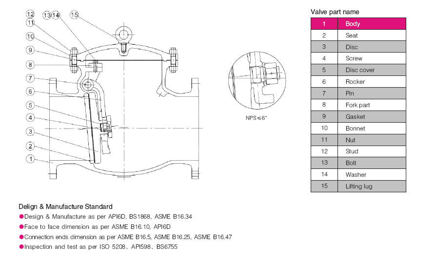
Swing Check Valve Parts: Identification, Function, and Maintenance
System operating conditions, fluid characteristics, line velocity, and installation orientation determine the appropriate component styles and construction materials for any piping assembly. Selecting durable internal trim and maintaining strict inspection practices keeps these mechanical elements operating smoothly across demanding industrial systems.
Operating Principles of Swing Check Valves
A swing check valve operates as an automatic directional flow device that requires no external actuation or manual intervention. Line media enters the valve body beneath the disc, exerting hydrodynamic pressure that lifts the disc off the stationary seat ring. This rotational motion swings the disc upward into the bonnet cavity, creating an unobstructed passage for continuous forward flow.
When line pressure subsides or the forward stream begins to reverse direction, the moving fluid no longer supports the weight of the disc. Gravity pulls the disc downward along its rotational arc toward the stationary seat. Media flowing backward immediately contacts the downstream face of the disc, driving it firmly against the seating surface to form a tight barrier against reverse travel.
- Forward fluid velocity lifts the disc assembly upward to open the waterway.
- Gravitational pull initiates closure as soon as flow velocity drops near zero.
- Reverse line pressure forces the disc against the seat to seal the fluid chamber.
- Internal stops inside the bonnet prevent the hinge arm from traveling past top dead center.
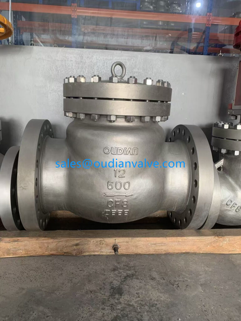
Installed swing check valves rely on line fluid dynamics and gravity to actuate the internal closure disc.
Primary Swing Check Valve Parts and Internal Anatomy
The internal anatomy of a swing check valve contains distinct structural and functional components working together inside a pressurized housing. Each part handles specific mechanical stresses, chemical exposures, and thermal cycles throughout standard operation.
While design configurations vary according to pressure class and nominal line size, the core assembly consistently features stationary pressure boundaries paired with dynamic internal closure elements. Maintaining these individual parts in clean, calibrated alignment prevents premature valve seizure and system backflow.
Pressure Boundary Parts
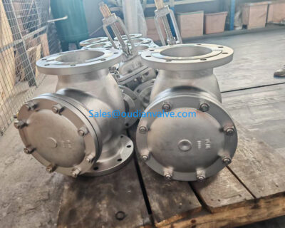
The valve body and bonnet form the rigid external shell that retains internal system pressure. These parts contain the flowing media and provide secure mounting cavities for the internal mechanism.
Dynamic Flow Parts
The disc and hinge arm constitute the movable assembly that swings open or closed based on fluid movement. Precision pivots keep the disc aligned squarely with the stationary seating plane.
Sealing and Retaining Parts
Gaskets, seat rings, hinge pins, and body studs prevent external leakage and seal internal reverse flow. These components absorb repetitive impact and thermal expansion during cyclic service.
Valve Body Construction and End Connection Types
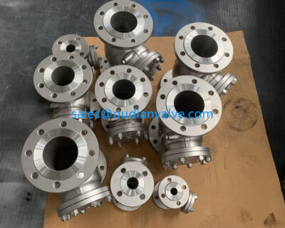
The valve body serves as the main structural pressure boundary, directing fluid through an engineered internal waterway. Manufacturers cast or forge the body with heavy walls capable of containing specified pipeline pressures and withstanding line stresses transmitted from adjoining piping. The internal contours minimize turbulence while offering sufficient interior clearance for the disc to swing clear of the primary flow path.
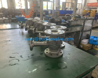
End connections cast directly into the valve body dictate how the unit integrates into the piping network. Common configurations include raised-face flanged ends, flat-face flanges, female NPT threaded ports, and socket weld ends. Flanged bodies allow straightforward removal for field refurbishment, whereas welded ends provide leak-tight joints ideal for high-pressure or hazardous media lines.
Matching the valve body end style to pipeline connection specifications prevents physical stress on the casing and reduces the likelihood of external joint distortion during bolt makeup.
Machined internal flow passages inside the valve body maintain smooth fluid transit toward the seat.
The Bonnet and Check Valve Cover Assembly
The valve bonnet, commonly termed the check valve cover, caps the upper opening of the body casting. This removable cover grants technicians complete access to the internal chamber for maintenance, seat resurfacing, and part replacement without cutting the valve out of the line. The underside of the cover often incorporates an integral disc stop that prevents the swing arm from lodging in an over-extended position during high-velocity surges.
Design variations in valve covers correspond directly to the pressure requirements of the installation. Bolted bonnet designs utilize heavy stud bolts and perimeter gaskets for medium-to-large industrial lines. In contrast, smaller valves often feature threaded caps or union bonnets that simplify rapid disassembly in confined process skids.
Bolted Bonnet Assemblies
Bolted bonnets use high-tensile studs and perimeter fasteners distributed evenly around a heavy flange rim. This construction supports high hydrostatic pressures and allows reliable gasket compression during maintenance overhauls.
Threaded Cover Designs
Threaded caps screw directly into the neck of the valve body, using an internal gasket or o-ring to seal the connection. This layout minimizes overall footprint and reduces component count on small-diameter lines.
The Disc and Hinge Arm Assembly
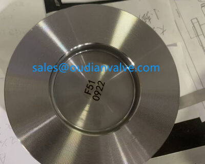
The disc functions as the primary movable barrier that checks reverse media flow. Supported by a rugged hinge arm, the disc plate swings through an arc from fully open to firmly seated. Modern designs often incorporate a loose disc connection on the arm stem, allowing the disc to rotate slightly and self-align against the seat face under closing pressure.
Hinge arms must combine structural rigidity with lightweight characteristics to react swiftly to changing velocity. Excessive arm mass creates high rotational inertia, which can cause severe slamming when reverse flow accelerates before closure occurs. Carefully balanced discs minimize turbulence, reduce system pressure drop, and lower the risk of structural stress along the hinge neck.
Self-Aligning Disc Features
- Slight mechanical float permits complete surface contact across the seat circumference.
- Even contact distribution reduces localized wear on sealing rings.
- Rotational flexibility helps clear minor particulate buildup from mating faces.
Rigid Mechanical Limitations
- Excessive disc weight can delay closure during rapid flow reversal.
- Fixed or unaligned disc attachments risk uneven peripheral contact and leakage.
- Severe fluid turbulence can cause disc flutter against the internal hinge stops.
Articulated disc and hinge arm assemblies allow smooth rotation toward the valve seat plane.
The Hinge Pin and Internal Support Bushings
The hinge pin serves as the stationary shaft around which the hinge arm rotates. In conventional valve bodies, the pin passes through machined holes in the casing wall and is locked in place with external threaded plugs and seal rings. Other designs position the pin entirely inside internal support brackets cast into the body or suspended from the bonnet, removing side-wall body penetrations.
Because the hinge pin absorbs repetitive mechanical shocks whenever the valve disc slams shut, it requires superior shear strength and galling resistance. Wear on the pin or hinge arm bore alters the alignment angle of the disc, preventing concentric seating against the stationary seat ring. Replaceable bronze or stainless steel bushings installed within the hinge arm bore reduce friction and protect the main pin from rapid dimensional loss.
Monitoring hinge pin clearance during scheduled maintenance prevents disc drooping, which is a leading contributor to mysterious seat leakage in aging piping loops.
Valve Seats and Sealing Surface Designs
The valve seat provides the critical mating surface against which the disc seals to arrest backflow. Depending on the service environment, check valves incorporate either integrated metal seats, threaded renewable seat rings, or resilient soft-seal inserts. The geometry of the seat must remain perfectly concentric with the disc swing path to prevent leakage pathways.
Choosing between metallic and resilient seating configurations involves balancing operating temperature, media abrasiveness, and required sealing tightness. Soft seats yield bubble-tight shutoff on clean liquids and gases, whereas metal seats provide reliable service in high-temperature lines carrying steam, hydrocarbons, or suspended particulates.
| Seat Type | Seal Material | Primary Strength | Operational Application |
| Metal-to-Metal | Stellite Alloy | High Heat Resistance | Hot water, steam, and abrasive slurry service |
| Soft Resilient | EPDM Rubber | Bubble-Tight Seal | Potable water and clean cooling fluid lines |
| Synthetic Seat | PTFE Polymer | Chemical Resistance | Corrosive chemical processing and solvent piping |
| Renewable Ring | Stainless Steel | Field Replaceable | Heavy industrial pipelines with scheduled overhauls |

Precision-machined seat rings establish a flat, uniform sealing surface across the fluid waterway.
Bonnet Gaskets, O-Rings, and Body Fasteners
External sealing relies on elastomeric o-rings or high-density gaskets compressed between the body and cover flanges. These static sealing elements prevent process media from escaping into the external environment under operating pressure. Gasket materials include compressed aramid fiber, flexible graphite, PTFE, and spiral-wound stainless steel with synthetic fillers.
Body fasteners, typically consisting of heavy hex bolts or double-ended studs paired with matching nuts, apply the mechanical force needed to energize the bonnet seal. Using fasteners with proper tensile ratings prevents bolt stretch under thermal cycles. Following manufacturer-recommended cross-bolt torque sequences distributes clamping force uniformly, preventing localized gasket crushing or bonnet flange warping.
- Spiral-wound metal gaskets withstand severe thermal cycling and line pressure spikes.
- Elastomeric o-rings provide rapid, reusable seals in lower-pressure modular valve designs.
- High-strength alloy steel studs resist elongation during fluctuating operational temperatures.
- Correct bolt lubrication promotes even preload distribution across all bonnet fasteners.
Material Selection for Swing Check Valve Components
Matching component metallurgy to the chemical composition, operating temperature, and erosion profile of the process stream is critical for component longevity. Selecting incompatible materials leads to accelerated galvanic corrosion between the disc, hinge, and body castings. Specifying matched trims or noble alloys for critical internal components protects moving surfaces from rapid deterioration.
Industrial swing check valve parts are commonly manufactured from bronze, cast iron, carbon steel, and forged stainless alloys. Bronze and brass offer dependable corrosion resistance in marine and potable water applications. Carbon steel bodies paired with 316 stainless steel internal trim deliver robust mechanical strength in oil, gas, and industrial steam networks.
| Component Part | Common Material | Primary Benefit | Typical Environment |
| Valve Body | Ductile Iron | Mechanical Shock Strength | Municipal water systems and wastewater facilities |
| Valve Body | Cast Carbon Steel | High Pressure Support | Refinery loops and industrial utility piping |
| Internal Trim | 316 Stainless | Pitting Resistance | Corrosive chemical and acidic process streams |
| Internal Trim | Aluminum Bronze | Saltwater Stability | Seawater cooling loops and marine piping |
Selecting compatible metallurgy for bodies and internal trim prevents galvanic degradation in harsh service.
Identifying Component Wear and Common Failure Modes
Piping systems subject swing check valve parts to continuous dynamic forces that gradually degrade mechanical clearances. Water hammer represents one of the most destructive failure modes, occurring when the disc closes abruptly against high reverse velocity. The resulting pressure wave can shatter cast iron discs, bend hinge pins, or crack body flanges.
Valve chatter occurs when line velocity is insufficient to keep the disc pinned firmly against its open stop. The disc oscillates rapidly in the fluid flow, causing mechanical pounding between the hinge arm, hinge pin, and body stops. This continuous friction erodes pin diameters, elongates the hinge arm bore, and leads to disc misalignment, persistent seat bypass, and chatter marks across the seating rim.
Audible knocking or rhythmic rattling from a check valve indicates flow turbulence and disc chatter, requiring prompt internal inspection before the hinge pin shears completely.
Step-by-Step Maintenance and Inspection Procedures
Performing regular internal inspections allows maintenance teams to refurbish valve trim before catastrophic breakdown disrupts plant operations. Before servicing any valve, technicians must depressurize, isolate, and drain the connected pipeline section completely. Adhering to systematic disassembly and cleaning procedures maintains part integrity and supports safe servicing.
Once the interior is accessible, technicians evaluate sealing surfaces, pivot clearances, and structural components for signs of erosion, pitting, or mechanical distortion. Replacing consumable seals and refacing worn seats restores reliable shutoff performance.
- Isolate the pipeline section, vent residual fluid pressure, and drain all media from the valve body chamber.
- Loosen bonnet fasteners gradually in a diagonal pattern, then remove the cover assembly and discard the old gasket.
- Inspect the disc and hinge arm assembly, verifying that the disc swings freely without lateral binding or excessive slop.
- Remove the hinge pin side plugs to extract the pin, hinge arm, and disc for thorough bench cleaning.
- Examine the seat ring and disc face for scratches, scoring, or chemical pitting, relapping metal surfaces if minor defects appear.
- Reassemble the internal parts using fresh hinge pin bushings, install a new bonnet gasket, and tighten fasteners to specified torque values.
Removing the bonnet grants full access to clean the seat, replace worn pins, and inspect disc articulation.
Selecting Compatible Replacement Components
Procuring replacement parts requires careful verification of the valve manufacturer, model series, nominal pipe size, and pressure class. Internal dimensions, pin shaft diameters, and seat tapers are rarely interchangeable across different valve brands. Relying on original manufacturer equipment drawings and bill-of-materials documentation prevents installation delays.
When updating valve trim, operators should verify that replacement materials match or exceed the original engineering specifications. Upgrading from standard elastomeric seals to advanced fluoroelastomers or transitioning from carbon steel to stainless steel pins can extend service intervals in demanding chemical or high-cycle applications.
Verify Valve Nameplate
Record the nominal diameter, pressure class, body casting material, and series code stamped directly on the exterior valve identification plate.
Confirm Trim Numbers
Match the internal trim code to ensure that replacement discs, seat rings, and hinge pins share compatible metallurgy and mechanical hardening.
Replace Full Seal Sets
Install matching gasket sets, hinge pin seals, and seat inserts simultaneously whenever opening a valve body for internal service.
Frequently Asked Questions About Swing Check Valve Parts
What causes a swing check valve disc to separate from the hinge arm?
Continuous valve chatter and hydraulic water hammer subject the disc connection stud and retaining pin to severe cyclic fatigue. Over time, mechanical vibration loosens the fastening nut or shears the cotter pin, releasing the disc into the pipeline flow.
Can a swing check valve operate in a vertical pipeline?
A standard swing check valve functions in a vertical line only when fluid flow travels vertically upward. Downward flow prevents gravity from closing the disc against the seat, which eliminates reverse flow protection.
What is the difference between an internal hinge pin and an external hinge pin design?
An internal hinge pin mounts entirely within the body or bonnet cavity, eliminating body penetrations and reducing potential leak paths to the atmosphere. An external hinge pin passes through the valve body walls, supported by side plugs that permit easier pin extraction and visual verification of disc movement.
How does an operator determine if a valve seat requires replacement or relapping?
Visual inspection under bright light reveals radial score marks, deep scratches, corrosion pitting, or erosion grooves across the seating face. Minor surface defects can be removed by hand-lapping with fine abrasive compounds, whereas deep gouges necessitate replacing the seat ring.
Why is bonnet gasket replacement mandatory every time the valve cover is removed?
Compressed gaskets experience permanent plastic deformation and loss of elasticity during their initial mechanical installation. Reusing an old gasket leaves micro-voids along the flange faces, creating an immediate path for high-pressure leaks.
What causes persistent seat leakage when the valve disc appears undamaged?
Wear on the hinge pin or hinge arm bore allows the disc to sag below the concentric center of the seat ring. This angular misalignment prevents uniform perimeter contact, permitting fluid to bypass the lower or upper edge of the closure interface.
Summary of Swing Check Valve Maintenance
Reliable backflow prevention depends on the mechanical condition of individual swing check valve parts working in harmony under fluid pressure. Routine inspection of the disc, hinge pin, and seating interfaces prevents minor mechanical wear from escalating into severe line failures or pressure surges. Proactive maintenance and correct trim selection keep industrial fluid systems running smoothly and protect upstream pumping equipment from backflow damage.