

How Does a Check Valve Work
System designers select specific valve styles based on fluid velocity, line orientation, chemical compatibility, and allowable pressure losses. The correct configuration protects mechanical components like pumps and compressors from hydraulic shock and fluid contamination without requiring electrical actuators or human intervention.
How Does a Check Valve Work in Piping Systems
A check valve relies entirely on the upstream fluid pressure surpassing the downstream pressure to create flow. When fluid enters through the inlet side of the valve body, it presses directly against a movable closure element such as a disc, ball, or piston. This internal closure element stays held against a stationary valve seat until the incoming pressure overcomes both the resistance of the mechanism and any opposing downstream pressure.
The minimum upstream pressure required to move the closure member away from the seat is known as the cracking pressure. Once the incoming fluid reaches this threshold, the valve opens and establishes a continuous flow path through the internal cavity. As the fluid velocity accelerates, the closure member lifts further away, allowing the stream to pass smoothly through the discharge port with minimal turbulence.
Whenever upstream pumping ceases or downstream pressure increases, the direction of force reverses across the valve body. Fluid from the discharge side pushes the movable element back toward the valve seat, sealing the internal opening. Gravity and mechanical springs often assist this closing motion to block fluid travel before backward momentum develops inside the pipeline.
The valve seat forms the static contact surface that mates with the movable closing member. Resilient elastomer seals provide bubble-tight shutoff against low-pressure gas or clean water, whereas metal-to-metal seating surfaces handle abrasive slurries, aggressive chemicals, and elevated operating temperatures. Tight dimensional tolerances between the closure element and the seat keep reverse leakage to an absolute minimum.
Upstream pressure must continuously exceed both the mechanical closing force and the downstream backpressure to maintain an open flow path through any check valve.
Because check valves react purely to pressure changes inside the piping, they operate without external controls, sensors, or manual gearboxes. This self-actuating property makes the hardware dependable during unexpected power disruptions or sudden pump shutdowns. The continuous balance between inlet pressure and outlet pressure governs every movement of the internal disc.
Major Types of Check Valves and Internal Mechanisms
Check valves utilize distinct closure elements to manage different line sizes, flow velocities, and media characteristics. Selecting the appropriate design depends on system requirements, including allowable pressure drop, closing speed, and the presence of suspended solids in the fluid stream.
| Valve Type | Closure Element | Response Speed | Primary System Role |
| Swing | Hinged disc | Moderate | Suits large-diameter lines carrying clean liquids at steady flow rates. |
| Lift | Guided piston | Rapid | Handles high-pressure steam, gas, or clean liquids in horizontal runs. |
| Ball | Free sphere | Moderate | Controls viscous liquids, slurries, and wastewater containing solid particles. |
| Diaphragm | Flexible rubber | Very fast | Manages low-pressure chemical dosing and systems requiring quiet operation. |
| Spring-Loaded | Spring disc | Fast | Prevents water hammer across diverse mounting angles and varying flows. |
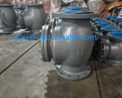
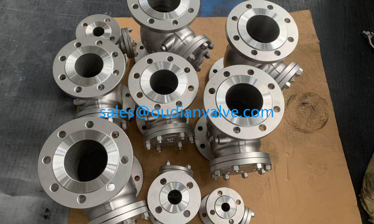
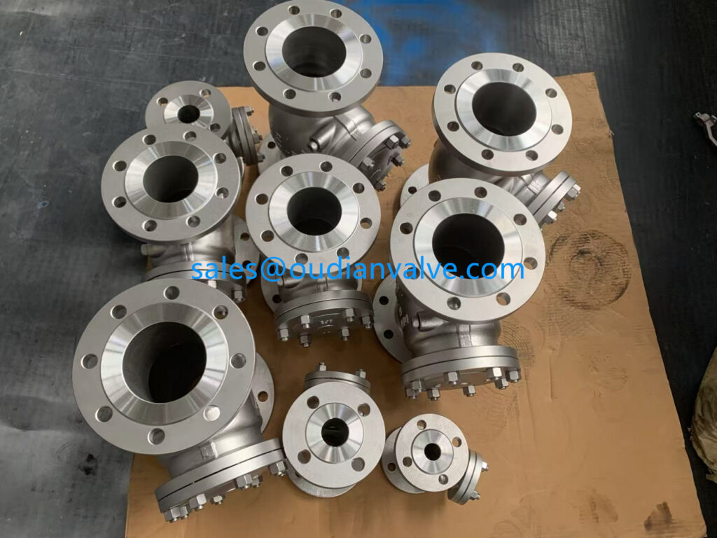
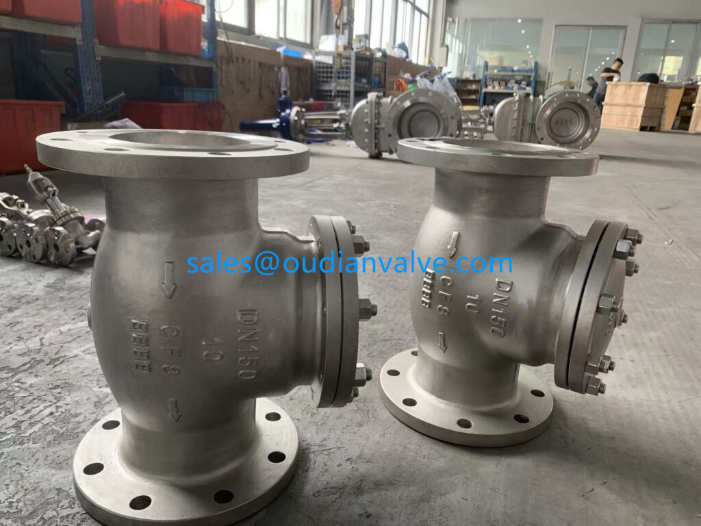
A swing check valve incorporates a disc mounted on a hinge pin located above the fluid passage. As forward flow increases, the disc swings upward into an open position away from the valve seat. When the flow rate slows and pressure drops, the weight of the disc causes it to swing back onto the seat, preventing reverse flow through the conduit.
A lift check valve operates similarly to a globe valve body, utilizing a guided disc or piston that rises vertically from the horizontal seat. Incoming fluid enters beneath the seat, lifting the piston into the upper chamber to clear the passage. Because gravity pulls the piston downward, conventional lift check valves require horizontal pipe installation unless paired with a spring assist mechanism.
Ball check valves employ an unattached spherical ball housed inside an angled or contoured body cavity. When forward fluid velocity increases, the ball rolls upward along internal guides into an off-center recess, leaving the flow path open. If flow declines, gravity or reverse pressure guides the ball back onto the circular seat ring, effectively sealing the orifice even when pumping wastewater or thick slurries.
A diaphragm check valve utilizes a flexible rubber membrane that flexes open under positive inlet pressure. Because the moving element contains no mechanical hinges or sliding stems, it resists fouling and operates silently under fluctuating flows. When inlet pressure drops, the memory of the elastomer returns the diaphragm against its seating rim, blocking backflow in sensitive liquid or gas lines.
A spring-loaded check valve features a mechanical spring positioned behind a disc, poppet, or split plates. The spring provides a constant closing force, ensuring the valve closes before reverse flow can gain velocity. This proactive closing mechanism minimizes hydraulic shock waves and allows the valve to operate reliably in horizontal, vertical, or angled piping layouts.
Industrial Applications, Advantages, and Design Limitations
Piping systems across manufacturing, municipal water treatment, energy generation, and residential plumbing incorporate check valves for equipment defense. Pumps rely on discharge check valves to prevent pressurized fluid from spinning impellers backward during sudden shutdowns. Compressors depend on check valves to isolate pressure vessels from upstream gas generation stages.
Water distribution networks position check valves at backflow prevention assemblies to stop non-potable liquids from entering clean drinking supplies. Sump pumps and sewage lift stations install ball or flapper check valves to prevent ejected wastewater from draining back into collection basins. Heating, ventilation, and air conditioning systems utilize inline check valves to maintain intended flow routing through hydronic loops.
Advantages
- Operates automatically without electrical wiring, pneumatic tubing, or manual monitoring.
- Protects rotating pump impellers, compressors, and pressure vessels from damaging backflow.
- Maintains hydraulic system prime by trapping fluid in vertical suction lines.
- Offers rapid response times to pressure drops when configured with internal springs.
Limitations
- Internal moving components cannot be visually verified without disassembly or acoustic tools.
- Restricts open flow area slightly, causing a minor permanent pressure drop across the valve.
- Vulnerable to slamming and severe hydraulic noise if sized incorrectly for line velocity.
- Debris entrapment on the seating surface can cause slow backward fluid leakage.
Despite their broad utility, check valves present distinct operational boundaries that designers must accommodate. Unlike gate or globe valves, standard check valves provide no external stem to indicate whether the internal disc rests in the open position or closed position. Plant operators must use ultrasonic monitors, pressure gauges, or downstream sight glasses to confirm proper internal movement.
Every check valve introduces flow resistance that creates an energetic head loss inside the piping. Swing check valves offer an unobstructed full-port design with minimal resistance, whereas spring-loaded lift or poppet valves extract higher pressure drops. Matching valve geometry to allowable pumping energy helps maintain system efficiency over prolonged operational cycles.
Critical Installation Considerations for Check Valves
Correct spatial orientation and mechanical alignment are essential for dependable check valve operation over long service intervals. Every check valve body features a cast or engraved arrow indicating the required flow direction. Installing the valve in reverse completely blocks forward flow while rendering backflow prevention useless.
Mounting angle plays a critical role in valve selection and performance. Standard swing check valves and gravity-assisted lift check valves require horizontal pipe runs so gravity can draw the closure element downward toward the seat. If installed in vertical lines with upward fluid flow, only spring-loaded or center-guided valves should be specified, as gravity alone cannot reliably seat the mechanism against fluid weight.
Placing check valves too close to turbulence sources causes premature mechanical degradation. Elbows, throttling valves, strainers, and pump discharges create swirling, irregular flow patterns that disrupt steady disc stabilization. This turbulence forces the internal disc to fluctuate erratically against the hinge or guides, leading to hinge-pin fatigue and noise.
Engineers recommend positioning check valves along straight runs of pipe away from fittings and flow disturbances. Maintaining straight, uninterrupted pipe diameters upstream allows fluid velocity to stabilize into a uniform flow profile. This steady stream holds the closure element firmly against its internal travel stops without fluttering during active pumping.
Orienting the cast flow arrow with the true fluid direction and providing straight pipe upstream prevents excessive disc flutter and premature hinge fatigue.
Piping supports must bear the mechanical weight of the valve body without transferring bending stresses to flanged or threaded joints. Pipe deflection distorts the internal seat alignment, preventing the disc from creating a uniform circumferential seal. Proper pipeline anchoring keeps internal sealing faces parallel and leak-free.
Common Failure Modes and Maintenance Practices
Check valves operate under continuous mechanical forces, making them susceptible to wear over extended duty cycles. Recognizing degradation symptoms allows operators to service hardware before catastrophic pipe failures or pump flooding occur. Regular monitoring forms the backbone of dependable fluid management.
- Reverse fluid leakage caused by abrasive particulate buildup or scale across the sealing seat.
- Water hammer shock waves resulting from slow-closing discs slamming shut after fluid reverses.
- Valve chattering and acoustic vibration caused by operating below the minimum flow velocity.
- Hinge pin or spring mechanical fatigue from persistent turbulence and cyclical disc flutter.
- Elastomeric seal swelling or degradation resulting from chemical incompatibility with process media.
Debris accumulation represents the primary cause of seat leakage in municipal and industrial environments. Foreign matter such as pipe scale, sand, or weld slag can lodge between the disc and the valve seat, holding the valve partially open. Installing upstream strainers screens out suspended solids and preserves clean seating contact.
Water hammer occurs when fluid momentum reverses before the check valve reaches its fully closed position. When the backward-moving liquid column abruptly impacts the closing disc, pressure spikes travel through the pipe, rattling supports and stressing fittings. Replacing slow-closing swing valves with fast-reacting spring-assisted check valves dampens this hydraulic surge by shutting the port the instant forward flow reaches zero velocity.

Valve chattering happens when the line velocity remains insufficient to hold the disc fully open against its travel stops. The closure element repeatedly strikes the seat and internal stops, generating noticeable metallic knocking sounds and wearing down internal pivot pins. Sizing the valve to actual operational flow rates rather than matching arbitrary nominal pipe sizes eliminates this unstable flutter.
Routine maintenance includes testing for downstream leakage during scheduled pump shutdowns and inspecting elastomeric O-rings for hardening or cracking. Technicians should verify that hinge pins rotate smoothly without binding and that internal return springs retain their specified resilience. Replacing worn internals during routine overhauls restores sealing performance and extends overall pipeline service life.
Frequently Asked Questions About Check Valves
What is cracking pressure in a check valve?
Cracking pressure is the minimum upstream fluid pressure required to lift the closure member off the valve seat and initiate flow. Once inlet pressure exceeds this calibration point, fluid moves freely through the valve body.
Can check valves be mounted in vertical pipes?
Check valves can be installed vertically if fluid travels upward and the valve incorporates a spring assist to drive closure. Standard swing check valves without springs should not be mounted vertically because gravity can prevent proper disc seating.
Why does a check valve make knocking or chattering noises?
Chattering occurs when fluid velocity is too low to hold the internal disc firmly in the open position. The disc repeatedly bounces between the open stops and the valve seat until flow velocity increases.
What causes fluid to leak backward through a check valve?
Reverse leakage typically stems from debris trapped across the valve seat, physical surface scratching, or chemical deterioration of elastomeric seals. Mechanical binding of the hinge or guide mechanism can also hold the disc partially open.
How does a check valve differ from a control valve?
A check valve operates self-reliantly based on fluid line pressure without external power or manual adjustment. In contrast, a control valve requires an external electrical, pneumatic, or manual actuator to adjust flow rates.
Summary of Check Valve Operation
A check valve relies on differential line pressure to enable forward fluid movement while preventing destructive reverse flow. Selecting the right internal closure style and verifying installation alignment protects pumping equipment and preserves pipeline integrity. Routine inspections of internal seats and moving mechanisms maintain reliable system isolation across diverse industrial environments.