


Swing Check Valve – Diagram, Types, and Applications
Structural Components and Diagram Analysis
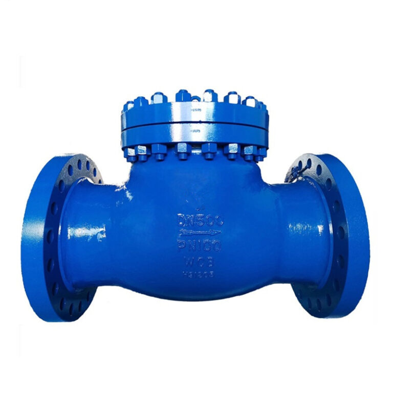
Understanding a swing check valve diagram requires examining the internal flow path and the mechanical arrangement of the movable closure member. The standard assembly incorporates a pressure-containing body, a swinging disc, an internal hinge pin, a seat ring, and a removable access bonnet.
The valve body houses the internal cavity and defines the fluid conduit, utilizing a full-bore contoured profile that limits flow obstruction. An upper bonnet connects to the main body with bolting, allowing direct top-entry access for internal inspection and seat replacement without severing the valve body from the surrounding pipeline.
The closure member consists of a disc suspended from a hinge arm that pivots freely around a stationary hinge shaft anchored inside the body walls. Sealing occurs where the machined face of the disc meets the mating surface of the seat ring, which may be integral to the casting or pressed into place as a threaded or welded insert.
| Component | Assembly Role | Primary Function |
| Valve Body | Pressure Boundary | Contains fluid pressure and provides the flow channel. |
| Valve Bonnet | Top Cover | Enables internal maintenance without cutting pipe. |
| Valve Disc | Closure Member | Swings to block backflow or permit forward flow. |
| Hinge Shaft | Pivot Pin | Supports the swinging arc of the disc assembly. |
| Seat Ring | Sealing Interface | Forms a tight seal against the mating disc face. |
Internal geometry plays a fundamental role in maintaining low drag coefficients, typically calibrated between 0.5 and 1.2 across full-port configurations. The streamlined flow passage minimizes turbulence, preventing excessive line drag while keeping the disc elevated during normal pumping operations.
Operating Principle and Fluid Dynamics
Swing check valves operate entirely on line thermodynamics and fluid momentum without requiring external electrical, pneumatic, or manual actuation. Unidirectional movement relies on differential pressure across the closure member combined with gravitational forces acting on the hanging disc.
When media flows downstream, positive fluid pressure exerts force against the upstream surface of the hanging disc. Once differential pressure reaches the minimum opening threshold, typically 0.5 psi in standard horizontal arrangements, the disc lifts away from the seat ring.
The disc swings upward around the hinge axis through an angular travel arc between 60 degrees and 90 degrees, resting against an internal travel stop in the fully open state. Stable flow velocities hold the disc in this elevated posture, clearing the bore to provide an unobstructed media channel.
- Forward fluid displacement imparts continuous dynamic lift to overcome the gravitational tare weight of the suspended disc.
- Velocity drop or pump shutdown diminishes upstream thrust, prompting the disc to descend under gravity toward the seat.
- Reverse fluid pressure drives the disc firmly into the seat ring, establishing tight mechanical closure within 0.3 seconds.
Rapid seat engagement blocks reverse flow and safeguards upstream equipment against reverse rotation. The automatic operation provides continuous line protection during planned shutdowns and abrupt mechanical trips.
Technical Specifications and Pressure-Temperature Ratings
Industrial applications demand strict alignment between valve pressure-temperature ratings and actual process line parameters. Swing check valves are manufactured across standardized pressure envelopes to accommodate both light distribution utilities and extreme petrochemical processing loops.
Pressure ratings span from ASME Class 150 (PN10) up to ASME Class 2500 (PN400), with heavy-wall forged and cast configurations handling operating pressures up to 450 bar. Valve body wall thickness, bonnet flange bolting, and seal construction correlate directly with these designated pressure classifications.
Low to Medium Pressure
Class 150 to Class 300 ratings handle municipal water networks, HVAC circulation, and general industrial utilities under moderate pressures.
High Pressure Classes
Class 600 through Class 2500 bodies manage high-pressure steam extraction, oil transmission, and chemical synthesis loops up to 450 bar.
Thermal tolerances depend heavily on the seat construction and internal sealing elastomeric compounds. Metal-to-metal seated assemblies withstand operational temperatures ranging from -35°C to 450°C, making them suitable for superheated steam and thermal transfer fluids. Resilient soft-seated versions operate between -20°C and 230°C, providing bubble-tight shutoff on chemical and low-temperature fluid streams.
Standard bore dimensions range from DN15 (1/2 inch) for small sampling branches up to DN900 (36 inches) for large transmission mains, with custom dimensions available for heavy civil pipelines. End connections include raised-face flanged ends conforming to ASME B16.5 and ASME B16.47, threaded NPT and BSP ports for small lines, and butt-weld ends for high-pressure welded piping.
Material Selection for Body, Trim, and Sealing Elements
Selecting appropriate metallurgy and seating materials determines mechanical longevity, corrosion resistance, and sealing effectiveness. Component materials must resist mechanical erosion, chemical attack, and thermal degradation throughout the anticipated operating life.
Carbon steel grades like ASTM A216 WCB provide structural strength and impact resistance for non-corrosive hydrocarbons and industrial water lines. Stainless steel alloys, such as ASTM A351 CF8 and CF8M, offer chemical resistance against oxidizing media and dilute acids, while duplex stainless steels (2205 and 2507) resist chloride pitting in marine and offshore applications.
| Component | Material Grade | Application Match | Mechanical Attribute |
| Body & Bonnet | WCB Carbon Steel | Refineries & Steam | Tensile strength exceeding 450 MPa. |
| Body & Bonnet | CF8M Stainless | Chemical & Acid Lines | High austenitic corrosion resistance. |
| Body & Bonnet | Двухуровневая квартира 2205 | Brine & Seawater | Resistance to pitting stress corrosion. |
| Sealing Face | Stellite Overlay | High Temperature Steam | Surface hardness exceeding HRC 45. |
| Sealing Face | PTFE / Viton | Corrosive Fluids | Resilient bubble-tight elastomeric seat. |
| Hinge Pin | 304 Stainless | General Flow Loops | Yield strength exceeding 600 MPa. |
Trim parts, encompassing the hinge pin, disc hanger, and seat rings, face continuous wear and impingement from fluid velocity. Pins fabricated from precipitation-hardened alloys or 304 stainless steel prevent galling and resist rotational fatigue over extended cycling. Seat rings hardfaced with cobalt-base Stellite overlays reduce wire drawing and thermal erosion under severe steam throttling conditions.
Common Swing Check Valve Configurations and Variations
Variations of the basic swing check design resolve spatial constraints, mitigate water hammer, and streamline line maintenance across distinct piping layouts. Engineers choose between standard full-body, wafer, tilting disc, and Y-pattern arrangements depending on process criteria.
Standard Flanged Type
Features a spacious cast body with a bolted bonnet, providing a full-port flow path that minimizes head loss across municipal and industrial lines.
Wafer Swing Check

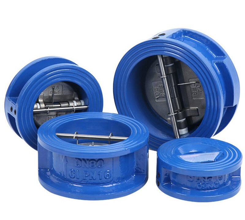
Clamps directly between companion flanges, using a short face-to-face profile that cuts installation space by half compared to standard bodies.
Tilting Disc Design
Mounts the disc at an inclined pivot angle between 15 and 30 degrees, reducing travel distance for faster closure and lower pressure drop.
The standard flanged valve remains common across general processing systems due to its robust construction and full-bore flow area. In contrast, the wafer swing check valve eliminates integral body flanges, clamping between pipe flanges to reduce overall weight and footprint, which proves valuable on marine vessels and offshore production decks.
Tilting disc swing check valves incorporate an offset pivot pin that positions the disc center of gravity close to the pivot axis. This geometry shortens the closing stroke, allowing the disc to respond rapidly as flow decelerates and decreasing the surge spike associated with reverse flow impact.
Y-type swing check valves feature an angled body branch that houses the disc mechanism. This layout provides an accessible inspection port, allowing technicians to inspect, lap, or replace internal seating surfaces without dismantling the surrounding pipeline.
Performance Advantages and Operational Limitations
Swing check valves provide distinct fluid-handling capabilities, though mechanical boundaries must be evaluated during engineering design. Balancing these characteristics determines whether a swinging disc matches the process system requirements.
Преимущества
- Full-bore internal geometry maintains high flow capacity and delivers low pressure drop.
- Automatic mechanical operation requires no external electric, hydraulic, or pneumatic power sources.
- Top-entry bolted bonnet allows direct internal servicing without cutting the valve out of line.
- Robust metallic disc construction handles solid-laden slurries and viscous industrial media.
Ограничения
- Susceptible to disc slamming and severe water hammer under sudden pump trip conditions.
- Pivoting disc requires minimum continuous line velocity to prevent chatter against the stop.
- Horizontal installation is preferred; vertical lines are limited exclusively to upward flow paths.
- Internal hinge pins experience mechanical wear over extended cyclic operational service.
The primary advantage of the swing check valve lies in its low flow resistance, as the disc swings completely clear of the central conduit. This open geometry decreases parasitic pumping losses, lowering long-term operating costs across continuous distribution loops.
Conversely, the relatively long angular stroke of a standard swing disc creates vulnerability to dynamic slamming. When forward flow collapses abruptly, backflow can accelerate down the pipe before the disc reaches its seat, producing severe hydraulic shock waves that damage piping hangers and adjacent instruments.
Swing Check Valves Compared to Alternative Check Valve Designs
Selecting an effective non-return valve requires comparing swing check mechanics against other common check valve geometries, such as lift check and dual-plate wafer models. Each mechanism presents trade-offs regarding response time, flow capacity, and mechanical wear.
Swing Check Attributes
- Full-bore passage minimizes internal head loss across high-volume pipelines.
- Accommodates fluids with suspended solids without blocking the pivot arm.
- Relies primarily on gravity and fluid reversal to drive closure.
- Top-entry bonnet permits inline servicing and component refurbishment.
Dual-Plate and Lift Check Attributes
- Spring-loaded plates close before flow reversal occurs, dampening water hammer.
- Compact wafer face-to-face dimensions reduce pipeline weight and footprint.
- Lift checks provide rapid shutoff on clean, high-pressure steam and gas lines.
- Internal guide ribs and central springs can trap particulates in dirty services.
Lift check valves employ a piston or ball that moves vertically away from the seat along internal guide tracks. While lift checks provide exceptional sealing on high-pressure steam and gas lines, their convoluted flow channels cause higher pressure drops, and solid particles can lodge within the guide mechanism.
Dual-plate wafer check valves use two semicircular plates mounted on a central hinge pin, supported by torsion springs. These plates close before flow velocity drops to zero, reducing hydraulic surge in high-head pumping systems, though their center pin obstructs mechanical pigging tools.
Industrial Applications Across Piping Systems
Swing check valves serve critical fluid control functions across municipal infrastructure, petrochemical complexes, and power generation stations. Their ability to handle diverse media makes them a standard fixture in both clean fluid circuits and contaminated slurry streams.
Petrochemical Refineries
Installed at discharge outlets of crude distillation pumps and vacuum towers to block backflow of hydrocarbons and volatile process fluids.
Municipal Water Networks
Applied in high-capacity booster pump stations and wastewater aeration tanks to protect supply pumps from downstream hydraulic heads.
Thermal Power Plants
Integrated into boiler feed lines, cooling water loops, and steam condensate return lines to maintain unidirectional thermal circulation.
In municipal water and wastewater treatment facilities, swing check valves handle raw sewage, activated sludge, and potable water. Their unobstructed bore allows fibrous materials and suspended solids up to 5 mm in diameter to pass without snagging on internal guides or accumulating behind the disc.
Within energy generation stations, swing check valves installed in cooling water piping isolate condenser units and prevent thermal siphon backflow. For cryogenic processing, extended-bonnet swing check valves handle liquefied natural gas at temperatures down to -196°C, maintaining positive shutoff on vapor return headers.
Engineering Selection Criteria for Piping Systems
Specifying a swing check valve involves calculating fluid velocity, line operating pressures, and media characteristics rather than matching the nominal line pipe diameter. Improper sizing remains the leading cause of premature internal wear and noisy valve chatter.
A valve sized purely by nominal line size often operates partially open when system flow runs below peak capacity. When fluid velocity is insufficient to keep the disc seated firmly against its upper travel stop, the disc oscillates within the fluid stream, causing rapid wear on the hinge pin and hinge arm.
Calculate minimum flow velocity to confirm that standard operating rates produce enough dynamic pressure to hold the disc fully open against its stop, typically requiring velocities between 1.5 m/s and 3.0 m/s for liquid media.
Media corrosiveness dictates trim and body materials, requiring austenitic stainless steel or nickel-based alloys for corrosive chemicals and seawater services. Highly viscous liquids, such as heavy fuel oils or industrial syrups, benefit from tilting disc or wafer patterns that lower opening resistance down to 0.3 psi.
Installation Best Practices and Orientation Requirements
Proper physical installation directly affects whether a swing check valve functions smoothly or suffers premature mechanical failure. Piping layout, support structures, and flow orientation must align with the mechanical kinematics of the internal swinging disc.
Standard swing check valves are engineered primarily for horizontal pipeline runs, where gravity naturally pulls the disc toward the seat ring during zero-flow conditions. When installed in vertical lines, flow must always travel upward so gravity assists closure when the pump stops; installing a swing check valve in a vertical line with downward flow leaves the disc hanging open, preventing backflow shutoff.
Never install a standard swing check valve in a vertical pipeline with downward flow, as gravity prevents the disc from seating correctly and allows uninhibited media reversal.
Turbulent flow generated by upstream pipe fittings, elbows, strainers, or throttled valves induces rapid disc flutter and premature pin wear. Piping layouts should incorporate a straight pipe run of at least five pipe diameters upstream of the valve inlet to stabilize fluid approach velocity.
External pipeline stresses must not transfer to the valve body casting. Pipe hangers and rigid supports should be positioned within five pipe diameters of the valve flanges to eliminate piping bending moments and prevent seat distortion.
Inspection, Maintenance, and Troubleshooting Procedures
Regular maintenance regimens preserve the sealing performance of swing check valves and detect component wear before unplanned line disruptions occur. Routine visual inspection, leak quantification, and component refurbishment form the basis of effective plant maintenance.
Visual inspections every six months should examine the external valve body, bonnet gasket joint, and hinge shaft plugs for leakage or signs of corrosion. On valves equipped with external counterweights or dampening cylinders, technicians should verify free travel by manually moving the external lever arm.
Routine visual inspection of bonnet bolting and hinge pins helps identify component wear early.
- Depressurize and drain the pipeline segment before loosening bonnet bolts for internal service.
- Remove the bonnet to inspect the disc face, seat ring, and internal hinge pin for erosion or mechanical grooving.
- Check the hinge pin clearance; excessive play indicates pin or bushing wear requiring replacement.
- Lap lightly worn metal-to-metal seating surfaces with fine diamond compound to restore sealing contact.
Common operational issues include disc chatter, seat leakage, and failure to open fully. Disc chatter stems from low line velocity and can be resolved by installing an appropriately sized valve with reduced port dimensions. Excessive seat leakage points to trapped particulates or scratched seating surfaces, which can be corrected by flushing the system or machining damaged trim surfaces.
Manufacturing Quality Control and Regulatory Standards
Industrial swing check valves must comply with rigorous international standards governing pressure-temperature ratings, wall dimensions, non-destructive testing, and shell sealing performance. These manufacturing standards establish uniform reliability across oil, gas, chemical, and municipal infrastructure networks.
Design and manufacturing compliance with API 6D, API 594, and ASME B16.34 confirms structural integrity, while leak testing according to API 598 verifies shell strength and seat tightness.
Hydrostatic shell testing subjects the valve body to 1.5 times the nominal cold working pressure to verify casting soundness, while low- and high-pressure seat tests evaluate closure integrity under 1.1 times the design pressure limit. Helium leak testing detects fugitive emissions on critical chemical services down to tight detection thresholds.
Non-destructive examination protocols, including ultrasonic testing (UT), radiographic inspection (RT), and magnetic particle inspection (MT), confirm the absence of subsurface casting voids, inclusions, and cracks. Following published technical guidelines, such as those detailed in the Swing Check Valve – Diagram, Types, and Applications reference, assists engineering teams in selecting certified valves built to international specifications.
Frequently Asked Questions About Swing Check Valves
Can swing check valves be installed in vertical pipelines?
Swing check valves can be installed vertically only when fluid flows upward. Installing them in vertical downward flow lines leaves the disc hanging away from the seat, preventing it from stopping reverse flow.
How does a swing check valve prevent backflow?
The valve prevents backflow by using a hinged disc that swings against a stationary seat ring when forward velocity drops. Reverse fluid pressure pushes against the back of the disc, sealing it firmly against the seat without external power.
What causes water hammer in swing check valve installations?
Water hammer occurs when a swinging disc closes slowly after forward flow has already reversed, causing the disc to slam shut against the seat. Using spring-assisted wafer valves or tilting disc designs helps suppress hydraulic shock.
Why does a swing check valve chatter during operation?
Valve chatter occurs when media velocity is insufficient to hold the disc fully open against its travel stop. The fluctuating fluid stream causes the disc to oscillate continually, wearing out the hinge pin and hanger.
How do you size a swing check valve correctly?
Sizing requires calculating minimum and normal media velocities rather than matching pipe diameter. Sizing the valve to achieve fully open disc positioning under normal flow prevents flutter and extends trim life.
Summary of Swing Check Valve Engineering
Swing check valves provide durable, self-contained backflow prevention across complex industrial and municipal piping systems. Matching disc geometry, seating materials, and valve sizing to actual system fluid dynamics protects pumping machinery, minimizes pressure drop, and supports stable pipeline operations.