


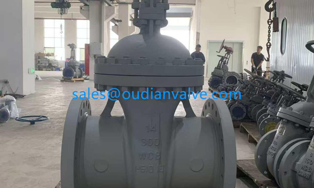
OS&Y Valve Design, Function, and System Applications
System operating pressures, fluid chemistry, overhead clearances, and local fire protection safety codes dictate whether an installation requires an outside screw design or an alternative gate mechanism. Understanding these operating dynamics helps engineering and maintenance personnel select appropriate valve assemblies for municipal, industrial, and emergency water supply networks.
What Is an OS&Y Valve and How Does It Operate?
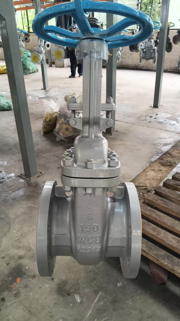
The term OS&Y stands for “outside screw and yoke” or “outside stem and yoke.” This terminology describes a valve architecture where the stem threads operate entirely outside the pressurized valve body and flow channel.
When an operator rotates the handwheel, the internal gate or wedge moves perpendicularly across the fluid stream to start or stop flow. Because the stem mates with a threaded yoke nut held stationary in the external frame, turning the wheel causes the stem to travel straight upward or downward rather than spinning within the fluid.
In the fully open position, the stem extends outward to its maximum height, clearing the internal conduit for unhindered flow. When closed, the stem retracts into the valve bonnet, pressing the gate firmly against the internal seating surfaces to establish a tight shutoff.
The exterior position of the stem threads prevents line fluids from washing away lubricants or depositing abrasive particulates on the operating mechanism.
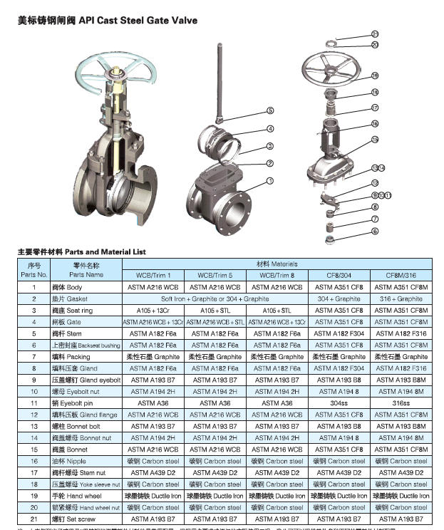
Core Design Features and Structural Components
The mechanical performance of an OS&Y valve depends on several distinct components working together to handle structural loads and line stresses. The primary structural elements isolate moving parts from line media while supporting high operating pressures.
The external yoke provides a rigid mechanical bridge between the bonnet and the operating handwheel. This structural framework resists torsional forces during manual actuation and keeps the stem aligned with internal guides during gate travel.
The exposed stem threads allow operators to lubricate the mechanism without depressurizing the piping system or disassembling the bonnet. Surrounding the lower stem, a bolted packing gland creates a resilient mechanical barrier that prevents process media from leaking around the moving shaft.
- Outside Stem: Serves as the primary visual indicator of valve position while isolating the mechanical threads from fluid exposure.
- Structural Yoke: Connects the bonnet to the drive nut, providing stability against line vibration and internal thrust forces.
- Operating Handwheel: Transmits rotational torque to the yoke bushing to lift or lower the gate assembly smoothly.
- Bolted Bonnet: Seals the upper cavity of the valve body while anchoring the yoke legs to resist internal operating pressures.
Supervisory Tamper Switches in Fire Protection Systems
Fire sprinkler systems and standpipes rely on unobstructed water supplies to suppress structural fires automatically. Installing an electromechanical tamper switch on an OS&Y valve helps monitor the open status of the main water control valve continuously.
The tamper switch housing mounts directly to the yoke framework, positioning an internal spring-loaded actuator rod against a designated groove in the valve stem. If an unauthorized individual turns the handwheel even a few revolutions toward the closed position, the movement displaces the rod and triggers a supervisory alarm at the building fire panel.
A closed or partially closed control valve prevents downstream fire sprinklers from receiving adequate water volume during an incident. In addition, an unnoticed partial closure can cause pressure loss throughout the piping system over time due to trapped air pockets or minor system leaks.
Building codes require supervisory tamper switches or physical locks on fire protection control valves to prevent inadvertent water shutoff.

OS&Y Valves Compared to Non-Rising Stem (NRS) Valves
Engineers primarily select between OS&Y designs and non-rising stem (NRS) valves based on available installation space and monitoring requirements. Both styles utilize internal gates to isolate flow, yet their stem kinematics and thread environments differ fundamentally.
An NRS valve houses its threaded stem directly inside the pressurized valve cavity. As the handwheel turns, the internal wedge climbs the rotating stem without changing the external height of the valve, making NRS models suitable for underground vaults or tight ceiling spaces.
However, NRS valves provide no external visual indication of gate position, requiring mechanical pointer indicators or physical torque checks to confirm status. By contrast, the OS&Y design displays open or closed status from a distance, though it requires vertical clearance to accommodate the rising stem.
| Особенность | OS&Y Valve | NRS Valve | Operational Difference |
| Position Check | Visual | Mechanical | Inspectors see gate position instantly from a distance on OS&Y models. |
| Thread Contact | External | Submerged | Internal line fluid contacts and corrodes NRS stem threads over time. |
| Height Profile | Variable | Constant | OS&Y units require substantial overhead clearance for the rising stem. |
| Fire Code Role | Preferred | Restricted | Life safety codes require exterior visual confirmation for main control valves. |
Technical Specifications and Construction Materials
OS&Y valves are manufactured across a wide array of dimensions, pressure classes, and metallurgy to withstand harsh industrial processes. Material selection depends on fluid compatibility, operating temperatures, and environmental corrosiveness.
Standard manufacturing covers nominal pipe sizes from 2 inches for localized branch lines up to 30 inches and beyond for large infrastructure trunks. Valve bodies are cast or forged from carbon steel, stainless steel, duplex stainless steel, and high-nickel alloys to resist aggressive operating conditions.
Pressure ratings for industrial assemblies span from ASME Class 150 to Class 2500, accommodating both low-pressure municipal lines and extreme high-pressure extraction systems. Standard assemblies accommodate operational temperatures ranging from -50°F up to 800°F, with external protective coatings applied to prevent exterior atmospheric corrosion.
Flanged Ends
Bolted flange connections allow straightforward assembly and removal in rigid industrial piping spools.
Welded Ends
Socket-welded and butt-welded joints eliminate potential mechanical joint leak paths in high-temperature service.
Threaded Ends
Female NPT threaded connections provide compact connections for low-diameter utility lines.
Inspection, Testing, and Maintenance Standards
Regulatory mandates such as NFPA 25 govern the inspection, testing, and maintenance of control valves installed in fire protection networks. Adhering to structured schedules prevents valve seizure and identifies mechanical defects before an emergency occurs.
Field technicians conduct routine visual assessments to verify that each unit remains fully open, structurally accessible, and free of external fluid leaks. Proper signage markings must remain legible, clearly identifying which section of the sprinkler system or facility the valve controls.
The monitoring method determines the minimum inspection interval for each installation. Control valves equipped with active supervisory tamper switches or physical padlocks require monthly visual checks, whereas unmonitored or unsealed valves require weekly walkthrough inspections.
- Verify physical accessibility to confirm that stored materials or construction work do not block emergency access.
- Check the exposed stem position and packing gland to identify packing leaks, stem damage, or thread corrosion.
- Confirm that supervisory tamper switch wiring connections, locks, and security seals remain undamaged and intact.
- Perform annual full-stroke operation to clear internal sediment and verify smooth mechanical travel through the yoke nut.
Industrial and Commercial Applications
Because the outside screw mechanism tolerates demanding operating cycles, OS&Y valves serve across several critical infrastructure sectors. The ability to verify valve status from ground level makes them an industry standard for fluid management.
Municipal water networks employ OS&Y gate valves across distribution mains, pumping facilities, and treatment plants. Operators managing broad utility manifolds depend on clear stem positions to balance flows, direct reservoir fills, and isolate broken distribution segments.
In upstream, midstream, and downstream oil and gas processing, these valves isolate crude oil, compressed natural gas, and refined petroleum products. Chemical processing plants and commercial HVAC steam networks also employ OS&Y assemblies to maintain fluid handling integrity across hazardous operating lines.
Industrial facilities utilize OS&Y valves on cooling tower loops and central boiler headers to facilitate rapid visual status checks during operational rounds.
Operational Advantages and System Limitations
Evaluating the mechanical characteristics of an OS&Y клапан reveals distinct operational strengths alongside specific physical constraints. Comparing these aspects helps piping designers integrate the correct valve style into their piping layout.
The primary advantage remains clear status verification without relying on electrical feedback or secondary position indicators. Furthermore, keeping the drive threads outside the fluid boundary prevents mineral deposition, scale formation, and fluid erosion from jamming the operating mechanism.
Conversely, the primary constraint involves the overhead clearance envelope required to accommodate the extended stem in the open position. Additionally, because the stem threads remain exposed to ambient weather and airborne dirt, unmaintained installations can accumulate external debris that damages the internal packing during actuation.
Преимущества
- Visual indication shows open or closed valve status from a distance.
- Operating threads remain isolated from corrosive or abrasive line media.
- Stem threads can be cleaned and lubricated during routine plant operations.
Ограничения
- Rising stem requires substantial overhead clearance in piping racks.
- Exposed threads collect airborne dust, grit, and outdoor weather exposure.
- Packing gland requires periodic adjustment to prevent minor stem weeping.
Frequently Asked Questions About OS&Y Valves
How can an operator tell if an OS&Y valve is open or closed?
An operator observes the position of the threaded stem protruding through the yoke. When the stem extends high above the handwheel, the valve is open; when the stem sits flush with or retracted into the body, the valve is closed.
Why are OS&Y valves common in fire protection systems?
Fire protection codes prioritize visual confirmation to confirm that emergency water lines remain open. The exterior rising stem provides immediate confirmation from ground level that the sprinkler water supply is unobstructed.
How often should an OS&Y valve undergo visual inspection?
Under NFPA 25 standards, valves with supervisory tamper switches, locks, or tamper seals require monthly inspection. Valves lacking supervisory monitoring devices require weekly physical walkthrough checks.
What is the main difference between an OS&Y valve and an NRS valve?
An OS&Y клапан has an exterior rising stem that moves upward out of the body as it opens, keeping the threads isolated from line fluid. An NRS valve keeps the stem at a fixed height while moving an internal gate along threads submerged within the flow.
What temperatures can standard OS&Y valves handle?
Depending on body metallurgy, trim selection, and packing materials, industrial OS&Y assemblies operate within temperatures between -50°F and 800°F. Always consult manufacturer ratings for specific media and thermal cycling limits.
Maintaining Valve Performance and Safety Compliance
OS&Y valves provide durable flow control and straightforward visual monitoring across vital municipal, commercial, and life safety networks. Regular lubrication of the exterior stem threads and routine testing under NFPA 25 standards keep control mechanisms responsive during emergencies. Establishing clear inspection logs and maintaining supervisory switches protects system pressures and supports long-term operational integrity.