


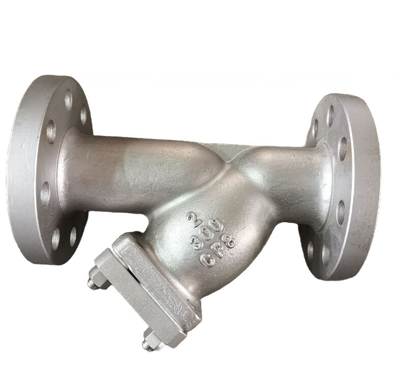
Y Strainer Specifications and Standards
Selecting the appropriate strainer requires matching physical pipe geometry, pressure ratings, screen perforation profiles, and metallurgy to the chemical and thermal demands of the process fluid. Piping codes and manufacturing standards establish exact testing boundaries, flange drillings, wall thicknesses, and material properties across industrial and commercial facilities. Engineering decisions depend on operating temperature, fluid velocity, allowable pressure drop, and regional regulatory compliance.
Operating Principle and Flow Dynamics
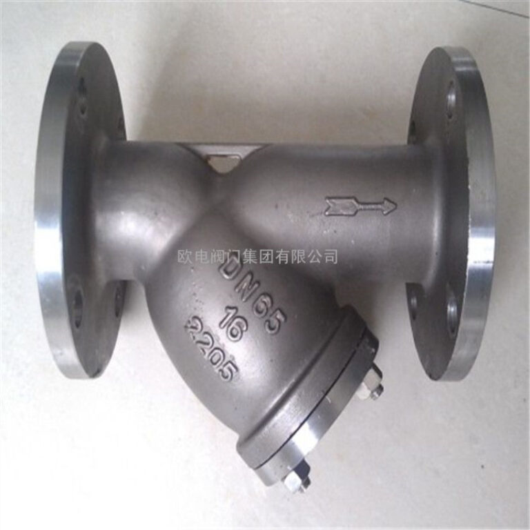
The internal geometry of a Y strainer directs incoming process fluid directly into an angled filtration chamber before exiting through the downstream port. Fluid enters the inlet nozzle, passes through the interior cavity of the cylindrical screen element, and flows outward across the media while solids accumulate within the interior pocket. This directional flow pattern protects the internal body surfaces from abrasive particle impact and concentrates debris within a contained collection pocket.
The angled branch typically sits at an angle relative to the pipeline axis, providing an optimal compromise between compact overall length and effective screen surface area. Fluid velocity decreases slightly inside the wider body cavity, allowing heavier solids to settle into the blind end of the screen without immediately blinding the open straining area. Because sediment collects inside the cylindrical screen basket, removing the cap or cover extracts the entrapped contaminants directly from the pipeline without dropping debris back into the stream.
Continuous monitoring of differential pressure between the inlet and outlet ports indicates screen loading, alerting operators before excessive restriction causes line starvation or mechanical collapse of the screen element.
The base of the screen pocket terminates in a removable cover plate or threaded cap, frequently drilled and tapped for a blow-off drain valve. Opening this blow-off connection allows line pressure to flush accumulated sediment out of the strainer screen while the system remains in operation. Routine blowdown purging reduces manual disassembly frequency in services carrying high particulate loads.
Core Engineering Specifications
Specifying a Y strainer requires establishing distinct mechanical parameters to confirm system compatibility and structural containment under peak operating limits. The nominal pipe size must align with adjacent piping runs, though high-viscosity applications occasionally require larger bodies fitted with pipeline reducers to moderate fluid velocities. Pressure classes define the maximum non-shock working pressure across broad temperature bands, dictating body casting wall thickness and bolting requirements.
Hydraulic calculations depend on the flow coefficient, which represents the volume of water flowing through the unit at standard temperature with a baseline pressure differential. Clean pressure drop varies across pipe sizes, body shapes, and screen opening dimensions, requiring verification during pump sizing to avoid excessive line resistance. Thermal limits depend on both the shell metallurgy and the secondary elastomer or metallic cover seals.
| Specification Metric | Engineering Impact | Evaluation Focus |
| Nominal Pipe Size | Line Sizing | Matches system piping diameter or requires reducers to adjust velocity. |
| Pressure Class | Pressure Rating | Dictates wall thickness, flange ratings, and hydrostatic test pressures. |
| Flow Coefficient | Capacity Sizing | Establishes hydraulic throughput relative to total differential pressure drop. |
| Thermal Envelope | Temperature Service | Limits maximum operating temperature based on shell metal and seal limits. |
Manufacturers determine flow coefficients by testing full-scale production bodies with water under controlled laboratory conditions. Engineers calculate predicted differential head losses across diverse specific gravities and viscosities using empirical correction curves published in technical catalogs. Neglecting viscosity corrections in heavy fuel or slurry piping leads to premature pump cavitation and reduced delivery rates.
Screen Perforations, Mesh Ratings, and Open Area
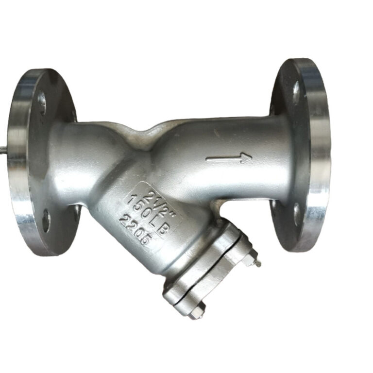
The straining element is the primary working component within the housing, fabricated as either a perforated metal cylinder or a dual-layer mesh assembly. Perforated screens are punched from flat sheet metal before rolling and welding into rigid cylinders, providing structural strength for rough debris separation. Wire mesh utilizes interwoven metallic wires to create tight microscopic apertures, almost always supported by a perforated backing cylinder to withstand differential pressures.
The open-area ratio represents the total cumulative surface area of screen holes divided by the internal cross-sectional area of the mating pipeline. A high open area minimizes pressure drop and lengthens operating periods between required screen cleanings. Low open-area ratios create rapid head loss as soon as light debris blinds a minor fraction of the open apertures.
Perforated Screen Media
- Constructed from punched heavy-gauge sheet metal
- High mechanical burst and collapse strength
- Well suited for pumps, cooling water, and coarse debris
Wire Mesh Elements
- Formed from woven stainless steel wires
- Captures fine particulate down to tight micron bands
- Requires a perforated structural backing sheet for reinforcement
Perforation diameters range from small circular openings suitable for light water service up to large apertures designed for coarse trash interception in raw intake lines. Wire mesh classifications run from coarse counts with large rectangular openings to fine weaves capable of retaining microscopic particles. Choosing an excessively fine mesh accelerates screen blinding, increases manual cleaning labor, and introduces structural risk from high differential pressure across unsupported filter fabrics.
Body and Component Metallurgy
Selecting shell, cover, and screen metallurgy demands rigorous evaluation of process fluid chemistry, temperature ranges, and external environmental corrosivity. Common body materials range from economical cast iron and ductile iron for low-pressure domestic water systems to carbon steel, low-temperature alloys, and austenitic stainless steels for demanding petrochemical systems. Specialized chemical piping requires nickel alloys, aluminum bronze, or duplex stainless steels to resist pitting, crevice corrosion, and aggressive acidic media.
Body material specifications reference standard metallurgy classifications, such as ASTM standards for casting and forging integrity. Screen elements require higher corrosion resistance than the pressure-containing shell, as screen wires have minimal thickness and suffer severe degradation from minor chemical attack. Most standard industrial strainers utilize stainless steel screens even when built with cast carbon steel or cast iron outer shells.
| Tipo de material | ASTM Standard | Common Application |
| Cast Iron | ASTM A126 | Non-critical commercial water systems and low-pressure utility lines. |
| Carbon Steel | ASTM A216 | High-temperature industrial service, steam lines, and hydrocarbon piping. |
| Aço inoxidável | ASTM A351 | Corrosive chemical plants, food processing, and cryogenic service lines. |
| Bronze Alloys | ASTM B62 | Marine seawater systems, brine handling, and potable plumbing runs. |
Cast bronze and aluminum bronze provide resilience against chloride attack in marine environments, raw river water cooling circuits, and brine piping. For high temperature service above standard limits, carbon steel or alloy grades maintain tensile strength where cast iron becomes brittle or prone to thermal shock failure. Gasket metallurgy must match the service, pairing flexible graphite or stainless steel spiral wound gaskets with high-temperature flanged covers.
Connection Styles and Dimensional Standards
Y strainers connect to piping systems using standard mechanical interfaces designed around pressure containment, assembly accessibility, and pipeline structural requirements. Threaded connections are common in small bore piping, allowing simple installation using standard pipe threads. Flanged connections dominate larger pipeline sizes, providing reliable gasket containment, easy disassembly during major overhaul, and alignment stability.
Welded interfaces eliminate potential external leak paths in toxic, flammable, or ultra-high-pressure lines. Socket weld ends accommodate small diameters by receiving pipe ends directly into machined counterbores before applying a structural fillet weld. Butt weld ends align directly with beveled pipe walls for heavy-wall high-pressure utility lines, maintaining continuous pipeline strength across critical high temperature service.
Flanged Ends
Provide bolted connections with standard raised face or ring joint profiles, permitting simple field replacement in intermediate and large pipe diameters.
Threaded Ends
Utilize female tapered pipe threads for compact assembly in utility, pneumatic, and low-pressure commercial piping installations.
Welded Ends
Offer permanent hermetic joins using socket weld or butt weld profiles for severe high-pressure and hazardous process fluid containment.
Face-to-face and end-to-end dimensions follow published dimensional conventions to support interchangeable mechanical design across multiple equipment suppliers. Variations exist between long-pattern and short-pattern castings, requiring verification against piping layout drawings before field installation. Mismatched dimensions cause piping strain, flange misalignment, and gasket leaks during mechanical fit-up.
International and Regional Piping Standards
Engineering standards govern the design calculation, material qualification, dimensional uniformity, and pressure boundary testing of Y strainers across distinct jurisdictions. Regulatory authorities often mandate compliance with specific boiler and pressure vessel codes under statutory safety laws. In contrast, industry product standards provide voluntary manufacturing baselines that establish commercial consistency between competitive valve and strainer manufacturers.
Engineers must review the latest editions of relevant regional standards, as jurisdictional codes vary between North America, Europe, and Asia. In the United States, piping design codes govern industrial facility construction, while separate standards define valve pressure-temperature classes and flanged fitting geometries. International projects regularly encounter European Norms and International Organization for Standardization frameworks that govern face-to-face dimensions and hydrostatic test regimens.
| Governing Standard | Standard Category | Technical Scope |
| ASME B16.34 | Dimensional / Rating | Establishes pressure-temperature ratings, wall thicknesses, and shell requirements. |
| ASME B16.5 | Flange Geometry | Defines pipe flange dimensions, bolt patterns, and facing details for piping. |
| API 598 | Inspection / Testing | Specifies hydrostatic shell and seat pressure testing acceptance criteria. |
| EN 12516 | European Code | Defines shell design strength and calculation methods for industrial valves. |
Mandatory regulations include local legal codes such as the European Pressure Equipment Directive or regional boiler inspection acts, which dictate quality oversight, third-party certification, and material traceability. Voluntary consensus standards, such as those published by the Manufacturers Standardization Society, establish best practices for screen burst strength, marking conventions, and cleaning plug ratings. Verifying compliance requires auditing mill test certificates and manufacturer declarations against contract documents.

Interpreting Manufacturer Technical Datasheets
Manufacturer datasheets communicate critical mechanical boundaries, physical measurements, and performance curves essential for system integration. The primary section outlines body style, available end connections, pressure class ratings, and complete material bills of materials. Reviewing material notes confirms whether components such as cover studs, screen retainers, and blow-off plugs meet specified environmental corrosion requirements.
The core hydraulic data appears as a flow rate versus pressure loss chart, or as tabulated flow coefficients across varied screen perforation options. As screen aperture sizes shrink from coarse perforations to tight mesh weaves, the flow coefficient decreases, resulting in higher localized resistance. Datasheets also present pressure-temperature curves that illustrate derating requirements at elevated temperatures, proving that nominal ratings decrease as metal temperatures rise.
Always verify whether published pressure-temperature ratings refer to the cast metallic housing or the complete assembly including cover gaskets, screen seals, and optional blow-off ball valves.
Dimensional drawings provide overall face-to-face lengths, center-to-blow-off drop dimensions, screen removal clearance envelopes, and complete component weights. Sizing support hangers and piping layouts requires consulting these drawings to allocate adequate clearance for operators to slide the screen element out of the body during routine maintenance. Incomplete dimensional reviews can trap the strainer basket against floors, walls, or structural framing.
Sizing Criteria and Common Engineering Errors
A frequent error in piping design is line-sizing a Y strainer to match pipeline nominal diameter without performing rigorous hydraulic calculations. Oversizing can allow internal velocities to drop too low, allowing particulates to settle prematurely in upstream piping rather than reaching the collection basket. Conversely, undersizing produces excessive fluid velocity, elevated pressure drops, accelerated screen erosion, and potential acoustic noise in facility piping.
Fluid viscosity dramatically impacts strainer sizing, as heavy oils, syrups, and polymer solutions exhibit substantially higher friction across perforated and mesh media than water. Engineers apply empirical viscosity correction factors to adjust baseline flow coefficients and determine realistic differential pressure loss. Screen collapse is a serious danger when high-viscosity fluids pass across unsupported fine mesh, generating destructive differential pressures across the element.
Never size screen openings finer than necessary for downstream equipment protection; excessively small apertures blind quickly, causing rapid flow starvation and heavy maintenance cycles.
Another common mistake involves neglecting the chemical compatibility of cover gaskets and screen spot-welds in aggressive fluid lines. Exposure to incompatible solvents or acids causes localized corrosion of fine screen wires or premature gasket degradation, leading to bypass leakage or external fugitive emissions. Verifying all media components against comprehensive corrosion tables prevents unexpected field failures.

Pipeline Installation and Piping Orientation
Proper physical orientation ensures that gravity assists debris retention within the designated screen pocket rather than allowing particles to fall back into the active pipeline. In horizontal piping runs, install the strainer with its angled screen leg pointing downward to retain debris within the collection chamber. Installing the branch upward creates a settling trap inside the pipeline itself, rendering blowdown connections useless and re-contaminating the stream during screen extraction.
Vertical piping runs present distinct geometric constraints that limit workable strainer configurations to downward flow directions. Flow must enter the top of the body and travel downward into the screen so that collected particulates settle naturally toward the lower cap. Upward vertical flow causes solids to settle backward down the supply pipe, reducing screen efficiency and failing to protect upstream equipment during pump shutdowns.
- Inspect the body flow arrow casting to confirm correct orientation relative to system fluid travel before mounting.
- Mount the angled filter housing downward below the pipe centerline to facilitate natural sedimentation and blow-off flushing.
- Verify adequate physical clearance beneath the cover cap to allow full withdrawal and reinsertion of the screen assembly.
- Install isolation valves and calibrated pressure gauges immediately upstream and downstream to simplify routine maintenance and differential monitoring.
For steam or vapor lines, horizontal installations frequently require angling the screen branch sideways in the horizontal plane rather than straight down. Laying the leg horizontally reduces the risk of condensate accumulation within the pocket, which minimizes the incidence of damaging water hammer events when steam flow resumes. Consult application engineering manuals to align orientation with phase characteristics.
Maintenance Procedures, Blowdown, and Safety
Routine servicing restores filtration capacity and prevents screen deformation caused by elevated differential operating pressures. Facility operating procedures dictate whether lines utilize periodic blowdown clearing through bottom drain valves or manual basket extraction. Blow-off routines purge loose sediment rapidly, but sticky deposits, fibrous debris, and biological growth demand periodic manual screen removal and ultrasonic or chemical cleaning.
Personnel safety requires complete system isolation, depressurization, and temperature normalization before loosening bonnet bolts or removing threaded cover caps. Trapped high-temperature fluids or compressed gases present severe burn and impact risks during bonnet separation. Following verification of zero energy state, technicians systematically back off cover fasteners, inspect the sealing faces, extract the screen element, and evaluate the basket for structural tears or weld separation.
Automated Blowdown Maintenance
- Flushes loose particulate without interrupting process operations
- Reduces labor overhead and physical maintenance requirements
- Minimizes operator exposure to hot or hazardous fluids
Manual Screen Cleaning
- Requires complete pipeline isolation and fluid depressurization
- Consumes maintenance labor and requires replacement cover gaskets
- Exposes maintenance personnel to residual hazardous process media
Whenever technicians remove the bonnet cover, replacing the cover gasket helps maintain system integrity and prevents leaks upon restart. Reusing compressed fiber, PTFE, or spiral wound gaskets risks joint leaks, because compressed sealing elements lose elasticity after thermal cycling. Clean all seating surfaces thoroughly, inspect the internal body locating seats for erosion, and torque bonnet bolts in a star pattern according to engineering specifications.

Frequently Asked Questions
What is the difference between a perforated screen and a wire mesh screen?
A perforated screen consists of punched metal sheet with relatively large circular or slotted openings, providing structural strength for capturing coarse debris. A wire mesh screen utilizes woven metal wires to filter fine microscopic particulate and is usually wrapped around a perforated support cylinder to prevent collapse.
How does pipeline orientation affect Y strainer installation?
In horizontal lines, the screen pocket must point downward to trap debris within the chamber using gravity. In vertical pipelines, fluid must flow downward so collected particles remain in the basket rather than falling backward into upstream piping.
Why are Y strainers in steam service often mounted horizontally?
Orienting the screen leg horizontally in steam lines prevents condensate from pooling in the bottom of the strainer body. Preventing standing condensate minimizes the hazard of water hammer when steam flow resumes through the line.
What causes a strainer screen to collapse during operation?
Screen collapse occurs when heavy particulate accumulation creates an excessive differential pressure drop across the filter media that exceeds its mechanical burst strength. Unsupported fine mesh, high fluid viscosity, and deferred cleaning cycles increase the risk of structural screen failure.
How do you determine the correct screen opening size for equipment protection?
Select screen openings based on the maximum particle tolerance of the most sensitive downstream equipment, such as pump impellers, control valves, or nozzles. Sizing the screen finer than required causes rapid clogging and excessive pressure drop without providing practical mechanical benefits.
Systematic Strainer Selection and Specification
Specifying the right Y strainer requires balancing fluid properties, pressure and temperature limits, screen opening geometry, and governing engineering codes. Proper verification of body metallurgy, flow coefficients, and piping orientation helps protect downstream pumps and instrumentation while minimizing unnecessary pressure drops. Following structured installation guidelines and disciplined maintenance routines preserves pipeline integrity across commercial and industrial operating facilities.