


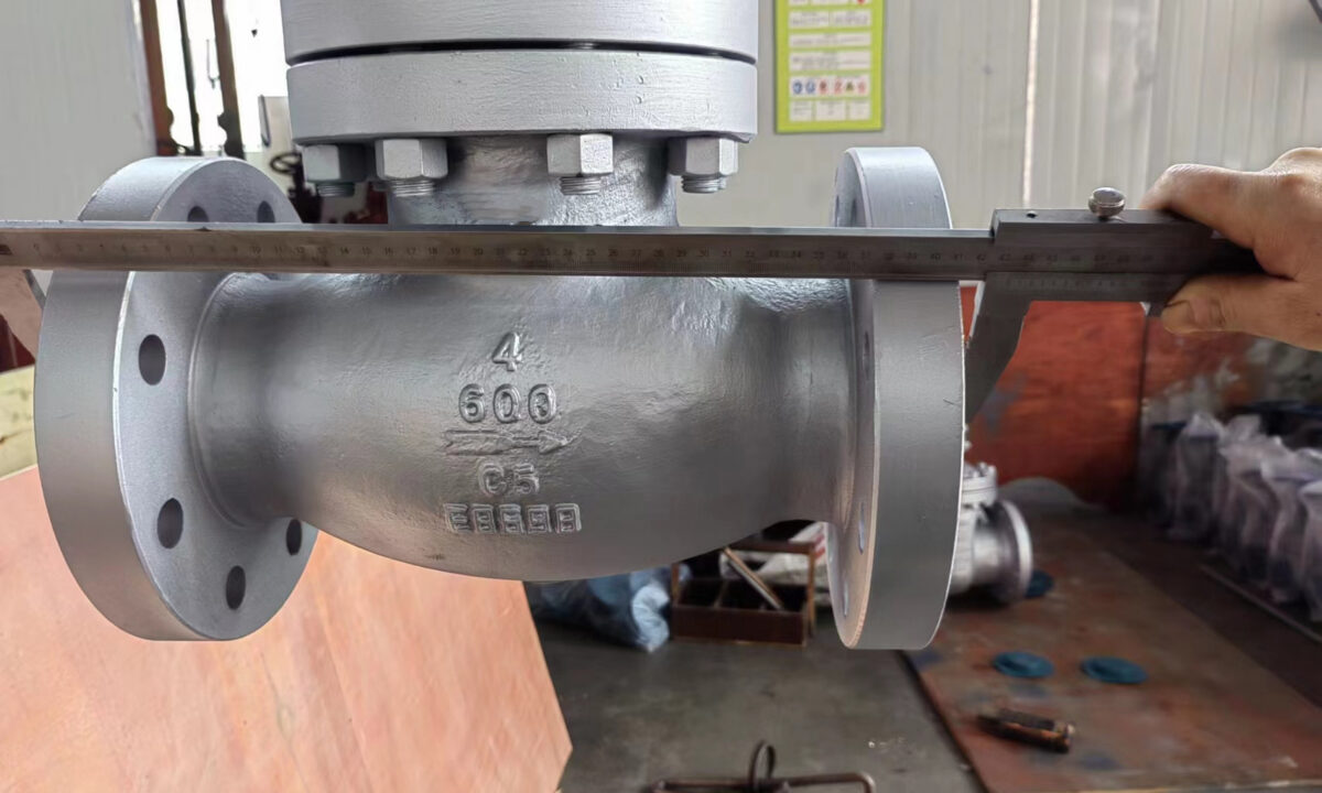
ASME B16.10 Valve Face-to-Face and End-to-End Dimensions: A Detailed Guide
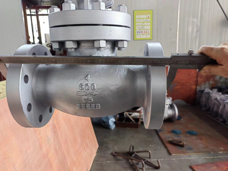
Standard Scope and Covered Valve Configurations
The ASME B16.10 standard establishes the physical envelope dimensions for both straight-way in-line valves and 90-degree angle valves across a broad range of pressure classifications. The standard covers cast and forged valve bodies made from steel, iron, and alloy materials utilized in chemical, oil, gas, power, and water distribution facilities.
Several standard valve designs fall under these dimensional provisions:
- Gate valves including wedge, parallel slide, and knife configurations.
- Globe valves encompassing standard straight, oblique, and stop-check body styles.
- Check valves such as swing check, dual-plate wafer check, and lift check mechanisms.
- Quarter-turn valves including flanged ball valves and high-performance plug valves.
- Butterfly valves in wafer, lugged, and double-flanged body patterns.
While ASME B16.10 standardizes installation lengths, the standard does not establish wall thickness limits, internal trim configurations, or pressure-temperature ratings. Mechanical design criteria and pressure containment boundaries remain governed by separate construction standards.
Standardized valve patterns enable consistent planning across diverse piping layouts.
Distinguishing Face-to-Face and End-to-End Dimensions
Piping layouts demand precise terminology when specifying valve overall lengths to prevent costly fabrication errors. Face-to-face dimensions describe flanged valves, whereas end-to-end dimensions define valves designed for welded or mechanical joint connections.
| Dimension Type | Datum Plane | Primary Application |
| Face-to-Face | Flange gasket faces | Installation of flanged valves between matching pipe flanges. |
| End-to-End | Extreme weld bevels | Welded spools using butt-weld or socket-weld valves. |
| Center-to-Face | Body centerline axis | Directional change connections using flanged angle valves. |
| Center-to-End | Body centerline axis | Welded transitions using butt-weld angle valves. |
For flanged valves with raised faces, the face-to-face length is measured between the contacting raised surfaces where the gasket seats. For ring-type joint flanges, the datum shifts depending on whether the measurement accounts for the raised metal face or the gasket pitch line inside the groove.
Center-to-Face and Center-to-End Layouts for Angle Valves
Angle valves introduce a 90-degree change in flow direction, making standard axial face-to-face measurements inapplicable. Dimensional tables for angle configurations establish the distance from the horizontal flow centerline to the vertical outlet face, and from the vertical centerline to the horizontal inlet face.
Center-to-face dimensions for angle valves dictate the precise location of piping elbows and support frames, requiring exact verification against standard tables before cutting pipe spools.
When an angle valve utilizes different end connections on the inlet and outlet, both center-to-face and center-to-end values must be identified. A common combination includes a flanged inlet with a butt-welding outlet, which requires cross-referencing separate dimensional columns within the standard.
Center-to-face dimensions dictate coordinate locations in piping models.
Standard Manufacturing Tolerances Across Nominal Sizes
Foundry casting, forging cooling rates, and final machining processes introduce minute length variations across valve bodies. ASME B16.10 accounts for these manufacturing variations by establishing permissible tolerances categorized by nominal pipe size and body orientation.
| Configuration | Size Bracket | Allowed Tolerance |
| In-Line Valves | NPS 10 and under | Permissible variation of plus or minus 1.5 mm. |
| In-Line Valves | NPS 12 and larger | Permissible variation of plus or minus 3.0 mm. |
| Angle Valves | NPS 10 and under | Permissible variation of plus or minus 0.75 mm. |
| Angle Valves | NPS 12 and larger | Permissible variation of plus or minus 1.5 mm. |
Tolerances apply to the finished valve prior to field coating or assembly bolting. Fabricators must incorporate these permissible variations into spool design allowances, particularly when multiple valves sit in close series along a rigid piping header.
Historical Revisions of the ASME B16.10 Standard
The standard has undergone continuous modernization to match evolving manufacturing capabilities and international piping conventions. Changes across editions affect table arrangements, metric conversions, and size ranges.
2000 to 2009 Updates
The 2000 edition incorporated standardized metric dimensions, while the 2009 revision removed obsolete numerical class markings and updated nonmandatory appendices.
2017 to 2022 Updates
The 2017 edition adjusted tolerances for large diameters, and the 2022 release integrated U.S. customary units directly into the primary tables alongside metric values.
Project documentation must specify the governing edition to eliminate conflicting inspection results. Errata published following major revisions provide critical corrections to table cells and reference headings.
Engineering specifications must reference the applicable standard edition year.
Influence of Body Pattern and Valve Type on Length
Valves sharing identical nominal diameter and pressure ratings often exhibit completely different overall lengths due to internal body geometries. A straight-through gate valve requires less internal flow chamber length than an oblique Y-pattern globe valve.
| Valve Design | Size | Class 150 Length |
| Válvula de gaveta | NPS 2 | Standard length of 178 mm or 7.0 inches. |
| Short Ball | NPS 2 | Standard length of 178 mm or 7.0 inches. |
| Y-Globe Valve | NPS 2 | Extended length of 216 mm or 8.5 inches. |
| Válvula de gaveta | NPS 4 | Standard length of 229 mm or 9.0 inches. |
| Short Ball | NPS 4 | Standard length of 229 mm or 9.0 inches. |
| Y-Globe Valve | NPS 4 | Extended length of 292 mm or 11.5 inches. |
Ball valves present an additional distinction between short-pattern and long-pattern envelopes. Short-pattern ball valves mirror solid-wedge gate valve dimensions, whereas long-pattern ball valves provide extra space to house seat springs or bleed ports.
Pressure Class Variations from Class 150 to Class 2500
Higher operating pressures necessitate thicker pressure-retaining walls, larger bolting circles, and expanded internal flow channels. Consequently, ASME B16.10 specifies longer face-to-face and end-to-end dimensions as pressure ratings escalate through Class 150, Class 300, Class 600, Class 900, Class 1500, and Class 2500.
Pressure class scaling directly increases physical valve length, meaning higher-rated valves cannot serve as direct dimensional drop-in replacements for lower-rated valves in rigid piping.
For example, a standard 2-inch gate valve expands in length as pressure class increases, moving from 178 mm in Class 150 up to significantly longer envelopes in Class 600 and Class 1500. Structural stability under extreme mechanical loads demands this extra valve body length.
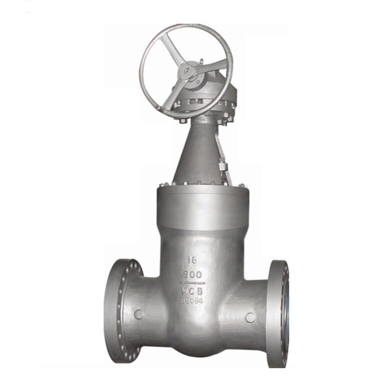
Higher pressure classes require greater body length to support structural wall thickness.
Impact of End Connections and Flange Facing Types
The selected connection style determines which dimensional table applies and shifts the external datum plane used during fabrication. Flanged, welded, threaded, and grooved ends each demand unique layout calculations.
Raised Face Ends
Raised face flanges measure across the raised contacting surface, which standard piping design software incorporates as the default face-to-face length.
Ring-Type Joints
Ring-type joint flanges incorporate a machined groove, altering overall face-to-face length depending on the required gasket ring height.
Butt-Weld Ends
Welded valves utilize end-to-end dimensions measured between root face bevel tips, matching the prepared pipe end for alignment.
Wafer and lugged valves introduce another configuration, relying on compact face-to-face envelopes clamped directly between line flanges by through-bolts. Because wafer bodies have no integrated flanges, their dimensions are governed by specialized compact tables within the standard.
Interaction with ASME B16.34, B16.5, and B16.11
Piping engineers must coordinate multiple technical publications to achieve a fully compliant valve assembly. ASME B16.10 functions exclusively as an envelope dimension standard, requiring cross-referencing with companion standards.
| Padrão | Technical Focus | Primary Scope |
| ASME B16.10 | Physical Envelope | Standardized face-to-face and end-to-end lengths. |
| ASME B16.34 | Pressure Integrity | Wall thickness, material ratings, and nondestructive testing. |
| ASME B16.5 | Flange Geometry | Bolt circles, facing finish, and hub dimensions up to NPS 24. |
| ASME B16.11 | Forged Fittings | Socket-weld depths and threaded fitting configurations. |
A valve matching the correct B16.10 length may still fail inspection if the flange bolt pattern does not comply with ASME B16.5, or if the pressure boundary lacks B16.34 certification. Combining these standards confirms both spatial fit and process containment.
Piping design requires coordination between dimensional and pressure boundary standards.
Engineering Applications in Layout and Spool Fabrication
Prefabricated piping spools constructed in specialized fabrication shops require precise dimensional tolerances to fit accurately into field piperacks. Designers embed ASME B16.10 values into 3D plant modeling software to establish piping coordinates, nozzle centers, and structural clearance boundaries.
Never pull misaligned piping flanges into position using flange bolts. Forcing flanged joints to compensate for dimensional errors introduces severe localized stress, causing gasket leakage, seat distortion, and nozzle damage on connected equipment.
Piping layout teams must also account for component accessibility. Installing an oversized valve in a tight corridor can block stem removal, prevent actuator mounting, or obstruct maintenance access to packing glands.
Accurate valve dimensions prevent mechanical strain during final spool bolt-up.
Multi-Parameter Valve Replacement and Interchangeability
Replacing an existing valve during plant maintenance requires more than matching nominal pipe size and face-to-face dimensions. Physical interchangeability does not equal operational equivalence.
Matched Parameters
- Exact face-to-face length avoids field cutting or welding on piping spools.
- Matching flange drilling allows reuse of standard bolting sets.
- Standard bore diameters prevent sudden localized pressure drops across the line.
Overlooked Risks
- Unmatched trim metallurgy accelerates corrosion in aggressive service.
- Different internal port geometries alter process flow coefficients.
- Oversized actuator packages may collide with adjacent pipe runs.
Prior to procurement, engineers must cross-check the existing valve tag, body material, pressure-temperature ratings, and flow characteristics. Verifying all operational parameters prevents unexpected operational shutdowns.
Field Measurement Protocols and Discrepancy Analysis
When original manufacturer drawings are unavailable, physical field measurements provide the necessary data for procurement and replacement. Personnel must execute site measurements methodically to avoid erroneous dimensional orders.
- Isolate, depressurize, and vent the piping system according to site safety protocols before touching installed components.
- Clean accumulated paint, insulation residue, and corrosion scale from the flange perimeter and joint gaps.
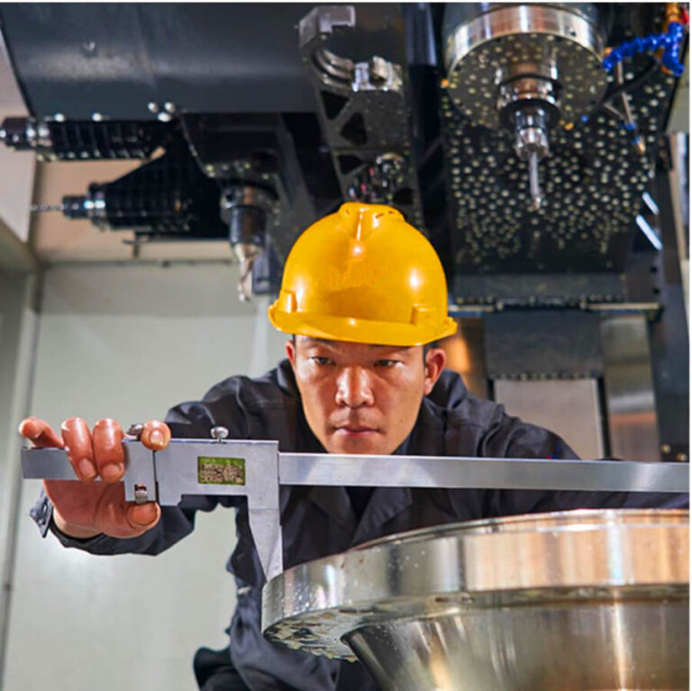
- Measure the outer metal-to-metal distance between mating pipe flanges using calibrated Vernier calipers or precision depth gauges.
- Subtract the estimated compressed gasket thickness from the measured gap to isolate the net valve face-to-face length.
- Cross-reference the resulting net dimension against the applicable ASME B16.10 table for the tagged size and rating.
Discrepancies between field measurements and standard tables often stem from compressed gaskets, flange face corrosion, or legacy nonstandard valve models. Any observed variance requires engineering evaluation before ordering replacement inventory.

Field measurements must isolate gasket thickness to verify true face-to-face dimensions.
Six-Step Valve Dimensional Verification Procedure
A systematic verification sequence helps piping teams confirm valve suitability prior to receipt inspection and final site installation. Following these sequential steps prevents late-stage installation delays.
Identify Design and Size
Confirm the valve pattern, body design, and nominal diameter against the engineering line list.
Verify Ratings and Ends
Check the specified pressure class and end connection styles against the piping specification.
Consult Standard Tables
Locate the governing ASME B16.10 table and note the required length and allowed manufacturing tolerance.
The remaining steps finalize technical compliance:
Fourth, examine the manufacturer General Arrangement drawing to verify that factory dimensions match the standard table value. Fifth, perform physical receipt inspection using calibrated tools to confirm the valve body falls within tolerance. Sixth, verify that physical clearances around the valve location accommodate handwheels, levers, or automated actuator assemblies.
Technical Procurement Checklist and Quality Records
Quality assurance programs require thorough documentation when procuring and receiving critical piping components. An incoming inspection checklist verifies that physical valves conform to engineering design parameters.
| Inspection Item | Verification Method | Acceptance Requirement |
| Face-to-Face | Calibrated Caliper | Conforms to standard table within published tolerance. |
| Flange Facing | Optical Surface Gauge | Surface finish matches specified microinch roughness. |
| Weld End Bevel | Bevel Angle Gauge | Bevel geometry complies with ASME B16.25 standards. |
| Tag Identification | Visual Nameplate Check | Size, class, and heat numbers match material test reports. |
Documenting verified dimensions in a formal inspection record creates an audit trail for plant safety files. For specialized fabrication questions or project support, technical specialists can be reached at sales@oudianvalve.com.
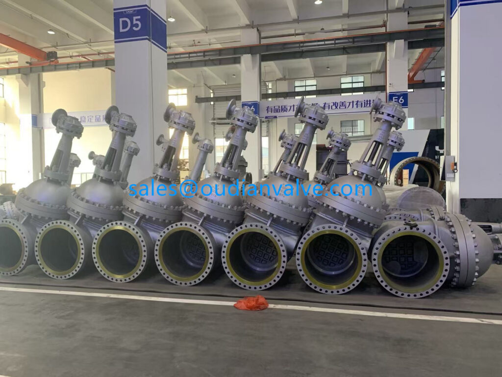
Quality records confirm dimensional compliance prior to plant delivery.
Frequently Asked Questions
Does ASME B16.10 establish pressure and temperature ratings for valves?
No, ASME B16.10 standardizes physical installation dimensions such as face-to-face and end-to-end lengths. Pressure and temperature containment ratings are established by ASME B16.34 based on body materials and wall thicknesses.
What is the difference between short-pattern and long-pattern ball valves?
Short-pattern ball valves share the compact face-to-face dimensions of standard gate valves to facilitate direct replacement. Long-pattern ball valves provide extended body lengths to accommodate internal cavity features, specialized seats, or secondary sealing mechanisms.
Why do butt-weld valves often have different lengths than flanged valves?
Butt-weld valves use end-to-end dimensions measured to the tips of the welding bevels, omitting flange hubs. Welding access, heat-affected zone clearance, and radiographic testing requirements often necessitate body lengths different from flanged designs.
Do all valve manufacturers use identical face-to-face dimensions?
Manufacturers producing valves certified to ASME B16.10 follow the same standardized dimensional tables within specified manufacturing tolerances. However, nonstandard, proprietary, or custom severe-service valves may deviate from standard tables, requiring verification of manufacturer drawings.
How does a ring-type joint flange affect the face-to-face measurement?
Ring-type joint flanges incorporate precision grooves for metallic sealing rings, altering the contact planes. ASME B16.10 provides dedicated dimensional listings for ring-joint valves that account for groove depth and gasket standoff distances.
Summary of ASME B16.10 Dimensional Compliance
ASME B16.10 establishes the dimensional framework that allows flanged, welded, and wafer valves to integrate into industrial piping layouts without mechanical mismatch. Proper implementation requires verifying the valve design pattern, nominal diameter, pressure classification, and connection type against the applicable edition tables. Applying systematic dimensional checks during procurement and fabrication protects piping systems from excessive mechanical strain and unexpected installation delays.