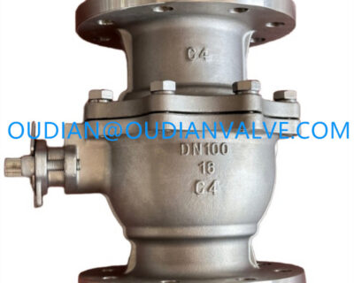


Types and Classification of Ball Valves
Types and Classification of Ball Valves
Ball valves serve as fundamental shutoff devices in fluid processing, utilizing a spherical disc to govern the passage of liquids, slurries, and gases. Through a quarter-turn rotational motion, these assemblies provide tight shutoff, low pressure drop, and swift mechanical isolation across high-pressure transmission networks and localized utility runs. Proper identification of the types and classification of ball valves allows process engineers to balance operational torque, maintenance access, flow capacity, and long-term containment integrity.
Fluid properties, operating pressure levels, temperature variations, and mechanical pipeline stresses dictate the appropriate valve configuration. Evaluating whether a piping run demands a floating ball, a trunnion-supported assembly, a multi-piece serviceable body, or specialized metal seating helps prevent premature component wear while supporting dependable isolation.
Operating Principles and Rotary Motion
A ball valve regulates fluid movement through a central spherical closure element containing a machined cylindrical bore. When the valve operator aligns the bore parallel to the pipeline axis, fluid flows smoothly through the conduit with minimal resistance. Rotating the operating stem ninety degrees turns the solid spherical face directly into the flow path, arresting line movement and creating a positive mechanical barrier against downstream piping.
The internal assembly relies on precision-machined seats positioned upstream and downstream of the ball to establish an impenetrable boundary. Stem packings maintain a tight seal around the driving shaft, preventing external fugitive emissions during rotation. Because the valve achieves full closure with only a quarter turn, actuation remains rapid compared to multi-turn linear rising-stem gate or globe valves.
The quarter-turn mechanism provides rapid line isolation, but opening or closing high-pressure lines too abruptly can create hydraulic shock or water hammer in rigid piping networks.
Classification by Ball Support: Floating and Trunnion Designs
The method used to support the internal spherical element serves as the primary structural classification for ball valves. Mechanical designers classify assemblies into floating ball valves and trunnion-mounted ball valves based on how internal fluid forces transfer to the valve body and sealing seats.
Internal ball support arrangements determine how operational pressure transfers across internal sealing surfaces.
In a floating ball valve, the ball connects solely to the operating stem at its top, leaving the base unconstrained within the valve cavity. Upstream fluid pressure pushes the floating ball downstream against the resilient outlet seat, compressing the sealing ring to form a tight closure. While this self-relieving sealing action functions dependably in low-to-medium pressure pipelines, extreme line loads can press the ball excessively against the downstream seat, driving operating torque upward and accelerating seal wear.
A trunnion-mounted ball valve anchors the spherical closure member at both the top stem and a bottom mechanical pivot known as the trunnion. Because mechanical bearings absorb the fluid load exerted across the sphere, the ball remains stationary along the flow axis. Spring-energized floating seats move against the stationary ball to establish isolation, allowing consistent operation under high working pressures and large nominal pipe diameters without generating extreme operational torque.
Floating Ball Valve Design
- Ball shifts downstream under medium pressure to seal against the outlet seat
- Compact construction with lower manufacturing complexity and lower initial cost
- Higher rotational torque under severe differential pressures
- Best suited for small-diameter pipelines and moderate pressure ratings
Trunnion-Mounted Ball Valve Design
- Ball anchored firmly by upper stem and lower trunnion pin
- Spring-loaded floating seats shift to seal against the anchored ball
- Lower operating torque under high differential pressure conditions
- Preferred for large-diameter pipelines, high pressures, and heavy transmission systems
Port Configurations: Full Port, Reduced Port, and V-Port
The internal diameter and geometric profile of the ball bore define the flow characteristics, velocity profiles, and pressure drop through the piping system. Selecting the proper bore geometry balances fluid friction losses against valve body mass and economic investment.
Bore geometry influences flow capacity, pressure drop, and pipeline pigging capabilities.
Full-port ball valves feature an internal flow passage matching the inside diameter of the connected piping. This unhindered pathway prevents flow restrictions, keeping head loss negligible and enabling mechanical scrapers or cleaning pigs to pass unobstructed during maintenance. Reduced-port ball valves utilize a flow passage one or two nominal pipe sizes smaller than the connecting pipe, which introduces minor pressure drops while lowering valve mass, seat dimensions, and operational torque requirements.
V-port ball valves replace the standard circular orifice with a contoured V-notch machined into either the ball or the surrounding seat. This geometry creates a linear or equal-percentage flow coefficient curve, transforming an on-off isolation device into an accurate throttling control valve. Cavity-filled ball designs fill the void between the ball and body cavity with resilient material, preventing process fluids or suspended solids from stagnating in dead pockets.
| Port Type | Flow Restriction | Pigging Capability | Primary Functional Benefit |
| Full Port | Negligible | Compatible | Minimizes head loss and permits inline mechanical pipeline cleaning |
| Reduced Port | Moderate | Incompatible | Reduces valve weight, physical envelope, and torque requirements |
| V-Port | Variable | Incompatible | Provides precise proportional flow control and predictable throttling |
| Cavity Filled | Baixo | Restricted | Eliminates stagnant internal cavities to maintain sanitary conditions |
Classification by Body Construction and Assembly
Ball valves feature diverse casing configurations that determine how technicians assemble, inspect, and service internal components. Body construction dictates structural stiffness, potential external leak paths, and the ease with which seats can be replaced during plant overhauls.
Body construction styles dictate field serviceability and external joint containment.
One-piece unibody valves cast or forge the main valve body from a single solid enclosure, inserting internal trim through an end plug. This arrangement eliminates secondary body flanged joints, minimizing potential fugitive emission paths while yielding an economical, compact unit that cannot be serviced once internal components wear out. Two-piece split-body assemblies divide the body into two sections joined by a bolted or threaded joint, allowing straightforward factory assembly, seat inspection, and moderate maintenance capability.
Three-piece ball valves consist of a central body housing flanked by two pipe end caps secured with external tie bolts. Technicians can loosen the fasteners, swing out the central body section, and replace seats or stem packings without detaching the end caps from the welded or threaded pipeline. Top-entry ball valves feature a removable bonnet on top of a single-piece body, providing complete access to the ball, trunnion, and seats for inline maintenance without cutting or unbolting the valve from the piping run.
- One-piece unibody assemblies provide rigid pressure containment with minimal joint leak paths for disposable utility service.
- Two-piece split bodies offer a balanced approach between structural rigidity, cost efficiency, and moderate servicing capability.
- Three-piece designs permit fast inline servicing by swinging the central valve cavity away from welded pipeline end connections.
- Top-entry cast or forged bodies allow complete inline trim replacement without disturbing pipeline alignments in heavy industrial installations.
- Fully welded bodies eliminate all external mechanical body joints, forming seamless pressure shells for buried pipeline transmission.
End Connection Types for Piping Integration
Connecting a ball valve to adjacent piping involves matching joint mechanics to system pressure, fluid hazards, vibration profiles, and routine maintenance practices. Mechanical connection styles directly influence installation duration and sealing integrity.
Flanged, threaded, and welded connections provide distinct benefits across varied operating environments.
Flanged connections join the valve body to matching pipe flanges via high-strength studs and perimeter gaskets. This design delivers robust mechanical resistance against pipeline bending moments, accommodates elevated pressure ratings, and allows convenient unbolting for shop refurbishment. Threaded female connections screw directly onto pipe ends, creating compact joints popular in small-diameter utility and plumbing lines, though mechanical threads remain prone to leakage under severe thermal cycling or pipeline vibration.
Welded connections provide permanent, hermetic joints that eliminate mechanical flange leak points entirely. Socket-weld ends receive pipe ends into recessed sockets for small diameters, whereas butt-weld ends match bevel-to-bevel against matching pipe walls for large, high-pressure runs. Welded connections resist high thermal fatigue and severe cyclical vibrations, but they complicate valve replacement and require careful heat management during installation to protect soft internal polymer seals.
Flanged Connection Advantages
- Simplifies valve removal and replacement during maintenance shutdowns
- Distributes mechanical pipe stresses evenly across perimeter bolt circles
- Supports elevated pressure classes and diverse gasket materials
Welded Connection Limitations
- Prevents straightforward mechanical removal without cutting pipe sections
- Demands certified welding procedures and non-destructive examination
- Poses risks of thermal damage to internal seats during initial installation welding
Actuation Methods: Manual and Automated Operation
The method used to drive the valve stem governs how quickly the closure member operates, whether systems can automate fluid routing, and how much operating torque can be delivered. Actuation arrangements range from direct manual levers to sophisticated process automation actuators.
Manual Hand Levers and Gearboxes
Small valves utilize simple hand levers for swift quarter-turn positioning, providing immediate tactile confirmation of open or closed status. Larger diameters or high-pressure valves employ multi-turn worm gearboxes to provide mechanical advantage, overcoming severe seat friction without overtaxing operating personnel.
Pneumatic Rack-and-Pinion Actuators
Pneumatic actuators utilize plant compressed air acting against pistons to deliver fast, dependable quarter-turn rotational force. These units suit emergency shutdown scenarios, fail-safe spring-return routines, and hazardous environments where electrical sparks must be avoided.
Electric Motor Actuators
Electric actuators integrate reversible electric motors, reduction gearing, and electronic position transmitters to manage valve travel. They integrate cleanly into distributed control networks, delivering precise remote positioning, continuous diagnostics, and automated modulating control.
Sealing Technology: Soft Seats versus Metal Seats
The interface between the spherical closure element and the surrounding valve body determines sealing tightness, friction coefficients, and allowable service temperatures. Material selection for internal seating rings establishes whether a valve delivers bubble-tight shutoff or endures abrasive media.

Seat material formulations define operational temperature boundaries and wear resistance.
Soft-seated ball valves utilize resilient fluoropolymers and elastomeric compounds, such as polytetrafluoroethylene, reinforced polymers, or synthetic elastomers. These compliant materials conform smoothly to microscopic surface deviations on the metal ball, yielding zero-leakage, bubble-tight isolation with low operating torque. However, soft polymers degrade, soften, or decompose when exposed to elevated process temperatures, abrasive particulate slurries, or intense chemical oxidation.
Metal-seated ball valves feature precision-ground metallic seats paired with hard-faced balls treated with tungsten carbide, chromium carbide, or satellite coatings. By maintaining metal-to-metal contact, these valves withstand extreme process temperatures, abrasive mining slurries, coking environments, and severe erosive flashing. Because hard metal surfaces lack elastomeric compliance, they require higher operational torque and precision matching to minimize allowable weeping rates.
Specifying soft seats for abrasive or severe thermal services can lead to rapid polymer extrusions and loss of shutoff, whereas metal seats provide durable wear resistance under harsh process conditions.
Body Materials: Carbon Steel, Stainless Steel, and Alloys
The valve body pressure envelope must withstand internal line pressures, external pipe loading, and corrosive atmospheric exposure. Metallurgy choices depend on the chemistry of the transported fluid, operating temperatures, and mechanical durability criteria.
Carbon steel provides high mechanical tensile strength and structural toughness, making it the workhorse material for non-corrosive hydrocarbons, steam systems, and structural industrial piping. Low-temperature carbon steels incorporate specialized alloying to prevent brittle fracture in cold climates or cryogenic refrigeration processes.
Stainless steel delivers high resistance against general corrosion, pitting, and acidic attacks, supporting pure fluid handling across chemical processing, pharmaceutical lines, and food manufacturing. For severe environments containing wet chlorine, high concentrations of hydrogen sulfide, or hot seawater, exotic alloys such as duplex stainless steel, nickel alloys, and titanium provide robust barrier defense against stress corrosion cracking.
- Cast and forged carbon steel bodies provide structural strength and economical containment for standard hydrocarbon processing.
- Austenitic stainless steels resist aggressive process media, atmospheric pitting, and cryogenic thermal embrittlement.
- Duplex and super duplex alloys combine high yield strength with elevated resistance to chloride-induced stress corrosion cracking.
- High-nickel alloys withstand aggressive acids, sour gas exposure, and severe chemical oxidation regimes.
Multi-Port Ball Valves: Three-Way and Four-Way Routing
Multi-port ball valves incorporate three or four pipe connections into a single valve body, using specialized bore drillings to divert, combine, or alternate fluid paths. This multi-directional capability simplifies complex piping networks by replacing multiple two-way isolation valves.

Multi-port ball valves streamline process piping by combining diverting and mixing functions into a single valve body.
Three-way ball valves utilize either an L-shaped or T-shaped internal bore to manage flow distribution. An L-port ball valve functions primarily as a diverter, directing fluid entering a central bottom inlet to either the left or right outlet port, but preventing simultaneous flow to both branches. A T-port ball valve offers greater versatility, allowing fluid from one line to split into two outlets, combining two incoming streams into a single discharge, or permitting straight-through flow with an option to divert sideways.
L-Port Diverting Function
An L-bore configuration channels flow from a common inlet toward one of two alternate branches, preventing simultaneous dual-branch flow and isolating systems during switching.
T-Port Mixing and Splitting Function
A T-bore configuration allows straight-through transit, simultaneous distribution across two outlets, or blending of two separate process streams into a combined discharge.
Industrial Applications Across Oil, Gas, and Chemical Processing
Diverse industrial environments depend on ball valves to manage process containment, fluid blending, and emergency safety isolation. Distinct operational environments impose unique design priorities on valve selection.
In upstream and midstream hydrocarbon transportation, trunnion-mounted, fully welded ball valves handle high-pressure natural gas and crude oil transmission. These assemblies provide reliable cavity isolation, double-block-and-bleed monitoring, and resistance to sour gas cracking. Refineries rely on metal-seated ball valves to isolate hot coking fractions, catalyst slurries, and cracking streams where standard polymer seats would degrade.
Chemical plants demand fluoropolymer-lined or corrosion-resistant stainless steel ball valves to isolate hazardous solvents, concentrated acids, and reactive intermediates. Water utilities, pulp and paper facilities, and commercial power generation facilities deploy full-bore and reduced-port ball valves for water distribution, steam isolation, condensate draining, and boiler feedwater regulation.
- Long-distance gas transmission uses trunnion-mounted ball valves with double-block-and-bleed capabilities for pipeline isolation.
- Chemical synthesis facilities utilize corrosion-resistant alloy ball valves to handle corrosive reagents and prevent fugitive emissions.
- Sanitary manufacturing facilities use cavity-filled stainless steel ball valves to prevent bacterial stagnation and maintain hygiene.
- Power generation plants employ heavy-wall forged steel ball valves for reliable high-pressure steam and cooling loop shutoff.
Operating Risks, Cavitation, and Leak Prevention
While ball valves provide durable shutoff, subjecting them to improper operating regimes introduces operational hazards. Recognizing mechanical failure modes helps plant personnel select appropriate trims and preventative accessories.
Using standard on-off ball valves for continuous throttling can lead to severe cavitation, localized erosion, and seat distortion. High-velocity fluid passing through a partially cracked spherical opening produces localized low-pressure zones where vapor bubbles collapse violently, pitting the metallic ball surface and tearing soft seat retainers. Specialized V-port or multi-stage cavitation-trim balls dissipate energy gradually, reducing the risk of acoustic noise and mechanical erosion.
Thermal expansion of fluid trapped within the body cavity presents another severe hazard in liquid service. When a closed ball valve absorbs heat from line steam tracing or ambient sunlight, the expanding trapped liquid generates immense hydraulic pressures that can distort seats or rupture the valve casing. Incorporating cavity-relief holes on the upstream ball face or using spring-loaded self-relieving seats vents excessive body pressure back into the process line.
Trapped liquids in a closed valve cavity can expand rapidly under heat, risking over-pressurization unless pressure-relieving seat designs or upstream equalization ports are specified.
Technical Criteria for Specifying Ball Valves
Selecting the optimal ball valve configuration demands a systematic review of fluid dynamics, operational frequencies, and maintenance environments. Aligning technical specifications with mechanical realities reduces lifecycle maintenance expenditures.
- Identify the chemical properties, phase, abrasiveness, and viscosity of the flowing process media to establish suitable body and seat metallurgy.
- Evaluate the maximum design pressure and continuous operating temperatures to decide between resilient soft seats and hard-faced metal seating.
- Determine whether pipeline scraping, minimal head loss, or precise throttling dictates a full-port, reduced-port, or V-notch ball geometry.
- Assess installation constraints, space envelopes, and maintenance requirements to select between one-piece, two-piece, three-piece, or top-entry bodies.
- Calculate required breakaway, running, and reseating torques to choose appropriately sized manual gearboxes, pneumatic cylinders, or electric motors.
Frequently Asked Questions
What is the difference between a floating and a trunnion ball valve?
A floating ball valve relies on upstream fluid pressure to push an unconstrained ball against the downstream seat to create a seal. A trunnion-mounted ball valve anchors the ball on upper and lower mechanical pivots, using spring-loaded floating seats to seal while minimizing operating torque.
Can standard ball valves be used for flow throttling?
Standard on-off ball valves are poorly suited for throttling because high-velocity flow across a partially opened round port erodes seats and causes cavitation. Specialized V-port ball valves provide contoured openings that permit controlled flow modulation without damaging internal trim.
When should a full-port ball valve be chosen over a reduced-port model?
A full-port ball valve should be selected when low pressure drop is essential or when pipelines require mechanical pigging for inspection and cleaning. Reduced-port valves suit applications where minor pressure drops are acceptable and smaller valve dimensions lower project costs.
What distinguishes three-piece ball valves during maintenance?
Three-piece ball valves feature a central body section that swings out or detaches after loosening external body bolts. This allows technicians to replace internal seats, seals, and the ball without cutting or unthreading pipe connections from the line.
Why are metal-seated ball valves used instead of soft-seated designs?
Metal-seated ball valves tolerate high temperatures, abrasive slurries, and severe erosive environments that would quickly melt, extrude, or tear soft polymer seats. They utilize hard-faced metallic components to maintain durable shutoff under demanding operating conditions.
Summary of Ball Valve Selection and Engineering Practices
Understanding the classifications of ball valves enables system designers to match ball mounting methods, port geometries, body styles, and seating materials to system demands. Evaluating operating pressures, chemical compatibility, line maintenance routines, and actuation methods supports dependable fluid containment across all industrial piping networks.