


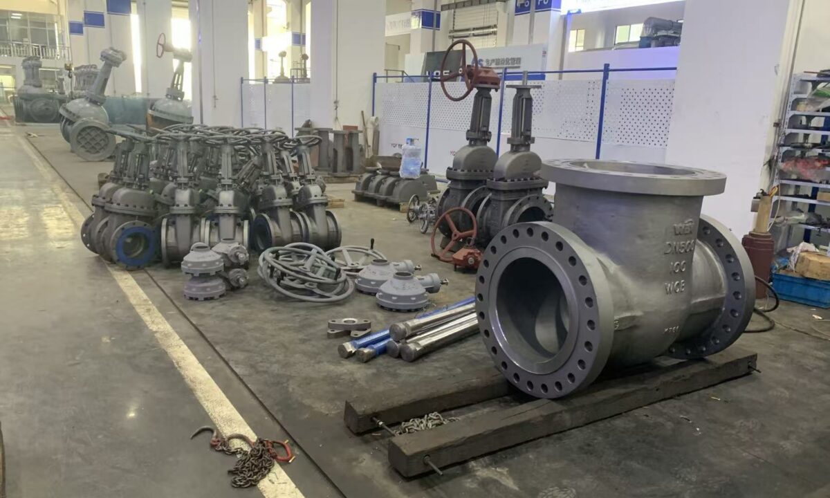
Valve Bonnet – Types, Leakages, and Repair
Selection of a bonnet configuration depends on line pressure, operating temperature, fluid compatibility, and maintenance frequency. Connection styles range from simple threaded caps to high-pressure self-sealing assemblies, each requiring specific gasket materials and assembly procedures to prevent fugitive emissions.
What Is a Valve Bonnet and How Does It Function?
The valve bonnet serves as a detachable cover that encloses the internal cavities of the valve body. As a critical pressure-containing component, the bonnet experiences direct exposure to process media. It provides the mechanical alignment and structural foundation for moving internals, including the valve stem, packing gland, and closure mechanism.
During manufacturing, the valve body is produced with an open top to allow machining of internal seats and insertion of the trim. The bonnet is mounted over this aperture once the stem and disc are positioned. Fastening the bonnet completes the pressure envelope, keeping the internal components in stable operational alignment.
Because the bonnet shares the internal pressure load with the body, its mechanical integrity determines the overall safety rating of the valve. The interface between the bonnet and the body requires precise machining to seat gaskets and maintain a tight seal under cyclic hydraulic forces. Bonnet thickness and geometry are engineered to resist deformation under both continuous line pressure and transient pressure surges.
The bonnet forms a removable pressure boundary that enables internal trim assembly while maintaining structural containment of pressurized fluids.
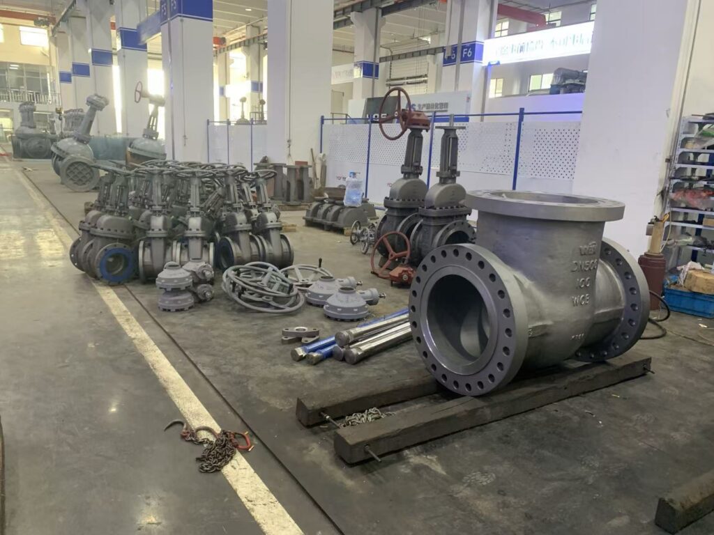
Bonnet-to-Body Connection Methods and Mechanical Joints
The attachment between the valve bonnet and valve body establishes a static pressure seal that prevents fluid from escaping into the environment. Engineers classify valve bonnets primarily by the mechanical joint design used to join these two major housings. The chosen joint style dictates the pressure limits, service life, and maintenance accessibility of the valve.
Each connection type uses distinct sealing principles, balancing leak prevention against disassembly convenience. Threaded joints rely on direct helical engagement, bolted joints utilize clamping preload against a compressible gasket, welded joints fuse the metals, and pressure seal joints leverage system pressure to energize internal seals. Selecting the correct mechanical connection prevents joint relaxation during thermal cycling.
| Joint Type | Pressure Range | Maintenance Profile | Primary Application |
| Enroscado | Bajo | Moderado | Plumbing and building heating systems |
| Welded | All classes | Difficult | Hermetic lines and disposable valves |
| Bolted | Medium to high | Accessible | Standard industrial processing manifolds |
| Pressure Seal | Class 600 to 4500 | In-line serviceable | High-pressure steam and extreme power piping |
Improper joint selection creates vulnerabilities where gasket displacement or bolt fatigue can lead to joint failure. Plant conditions involving thermal expansion, vibration, and fluid corrosiveness dictate whether a rigid welded joint or a serviceable bolted design is required.
Threaded Valve Bonnet Design and Operating Limits
A threaded valve bonnet attaches directly to the body through matched internal or external screw threads. This construction presents a compact footprint and economical manufacturing profile, making it common in light utility and non-critical services. The direct screw engagement provides a straightforward assembly process without requiring external hardware like studs or nuts.
Standard threaded joints present operational limitations caused by friction at the sealing surface. As the bonnet screws into position, rotational friction against the static gasket can cause scuffing or premature gasket wear. Friction-induced surface damage degrades the joint surface over repeated cycles of loosening and tightening, creating potential leakage channels.
Ventajas
- Simple mechanical structure with minimal components.
- Cost-effective production for compact industrial assemblies.
- Straightforward disassembly for routine shop cleaning.
Limitaciones
- Rotational friction during assembly risks gasket tearing.
- Required tightening torque escalates rapidly as diameter grows.
- Practical sizing generally restricted to nominal sizes of DN80 and below.
To reduce rotational wear, alternative designs incorporate a separate threaded union ring or collar. This collar tightens downward over the bonnet shoulder, converting rotational motion into purely axial clamping force on the joint surface. Even with collar modifications, threaded valve bonnets remain primarily restricted to nominal pipe sizes of DN80 and below due to torque constraints.
Welded Valve Bonnet Construction for Leak Prevention
Welded valve bonnets eliminate mechanical joints by permanently fusing the bonnet to the valve body. This full-penetration or fillet weld creates a hermetic seal that removes conventional gasket leak paths entirely. Welded joints provide strong resistance against high vibrational stress and continuous fluid pressure.
Because the welded joint is solid metal, it is not restricted by standard gasket operating temperature and pressure boundaries. The welded valve bonnet also avoids valve sizing limitations associated with bolt circle diameters or thread torque requirements. Welded bonnets serve reliably in critical environments where fluid escape cannot be tolerated under any circumstance.
- Hermetic joint eliminates fugitive emissions along the bonnet-body boundary.
- Operating parameters are not limited by gasket pressure ratings or thermal relaxation.
- Internal access requires cutting or grinding the structural weld seam.
- Commonly selected for disposable valves and long-duration maintenance-free installations.
The primary operational compromise of a welded connection is limited serviceability. Disassembling the valve to repair internal seats or replace the stem requires specialized cutting tools and shop re-welding. Some valve designs combine threaded joints with seal welding, providing mechanical load retention through threads and secondary fluid containment through the weld bead.
Bolted Valve Bonnet Design Across Industrial Pressure Classes
The bolted valve bonnet represents the most widely utilized connection style in industrial piping systems. This design uses matched flanges on the bonnet and valve body, held together by a circular array of heavy studs and nuts. Bolted bonnets accommodate virtually all standard pipe sizes and pressure classes encountered in process plants.
Clamping force generated by tightening the studs compresses an engineered gasket seated between the two flange faces. Gasket styles vary according to process parameters and include flat sheet, elastomeric, spiral-wound metallic, and solid metal ring-joint profiles. Controlled torque application creates uniform gasket seat stress across the circumference of the joint.
Standard bolt load-bearing capacity decreases drastically when operating temperatures exceed 600 degrees Fahrenheit (350 degrees Celsius), requiring thermal monitoring or seal welding.
As valve sizing and pressure ratings increase, bolted bonnets require heavier flanges and larger bolt diameters to resist separation forces. In applications operating above 600 degrees Fahrenheit (350 degrees Celsius), thermal expansion can cause bolt relaxation and subsequent leakage. In such severe thermal regimes, operators may hermetically seal-weld the flange perimeter to support the mechanical fasteners.
Pressure Seal Bonnet Mechanics in High-Pressure Applications
Pressure seal bonnets use internal system pressure to tighten the joint seal rather than relying solely on external fastener preload. This self-sealing geometry makes them suitable for high-pressure applications in pressure classes ranging from 600# to 4500#. As fluid pressure inside the valve body rises, it drives the bonnet upward against a dedicated thrust ring and sealing ring assembly.
The upward movement forces the sealing ring into a narrowing wedge formed by the bonnet outer diameter and the valve body inner wall. Higher system pressure produces greater compressive force on the sealing ring, enhancing joint tightness automatically. This mechanism contrasts sharply with conventional bolted flanges, where internal line pressure works against bolt preload.
Bonete de sello de presión
- Uses internal fluid pressure to compress sealing rings.
- Compact, lightweight profile in high-pressure classes.
- Pressure classes span from 600# up to 4500#.
- Requires fresh replacement seal rings following disassembly.
Bolted Flange Bonnet
- Relies entirely on external stud clamping force.
- Grows substantially heavier at higher pressure classes.
- Requires re-torquing to compensate for bolt relaxation.
- Utilizes standard sheet, spiral-wound, or ring gaskets.
Sealing rings in pressure seal bonnets commonly combine flexible graphite with stainless steel wire reinforcement. This composite material unites the sealing flexibility of graphite with the structural strength and corrosion resistance of stainless steel. Pressure seal designs also allow convenient maintenance access, as internal components can be withdrawn through the body opening once the segmented thrust ring is removed.
Bonnetless Valve Configurations and In-Line Maintenance
Bonnetless valves eliminate the bonnet assembly altogether, leaving the valve body as the sole pressure-retaining enclosure. By removing the traditional bonnet-to-body interface, this architecture eliminates the primary gasket leak path found in conventional valves. The reduction in mechanical joints makes bonnetless valves particularly beneficial in hazardous or high-vibration systems.
Access to internal components in a bonnetless design occurs through an integral box opening cast or forged directly into the valve body. This opening is engineered with sufficient clearance to allow the one-step insertion and extraction of internal trim parts. Maintenance personnel can inspect seats, guides, and closure elements without detaching heavy flanged assemblies from the line.
Bonnetless valves eliminate the bonnet-to-body gasket joint entirely, supporting rapid in-line maintenance and reducing total valve weight.
The absence of external bonnet flanges and bolting hardware results in a lightweight, compact valve profile. Despite their reduced mass, bonnetless valves maintain complete suitability for severe high-pressure service. In-line servicing capabilities minimize plant downtime during scheduled maintenance outages.
Materials of Construction and Compatibility Considerations
Valve bonnets are manufactured using either casting or forging processes, depending on valve size, pressure class, and service severity. Forged bonnets provide dense grain structures suitable for high-pressure service, while cast bonnets enable complex internal passages for larger nominal sizes. Both fabrication methods require sound metallurgical quality to prevent porosity and structural defects.
Bonnets are typically specified in material grades that match the valve body to prevent galvanic corrosion and differential thermal expansion. Pairing identical or chemically compatible alloys helps the bonnet and body expand at matching rates during rapid temperature swings. Common alloys include carbon steel, low-alloy chrome-moly steels, austenitic stainless steel, and specialty nickel alloys.
Hierro fundido
Economical material for low-pressure municipal systems, but vulnerable to cracking under mechanical impact.
Acero carbono
General industrial workhorse offering balanced tensile strength and structural ductility across moderate temperatures.
Acero inoxidable
Corrosion-resistant alloy suitable for aggressive chemical media, cryogenic systems, and high-temperature service.
Using dissimilar metals between the bonnet, body, and bolting can accelerate galvanic degradation in conductive process fluids. Engineers must also confirm that bonnet materials retain adequate fracture toughness at minimum operating temperatures. In severe services, non-destructive examination verifies material density prior to putting the bonnet into service.
Common Causes of Valve Bonnet and Joint Leakages
Because the valve bonnet and its body joint serve as pressure boundaries, they are susceptible to mechanical and thermal degradation over time. Leakage may develop directly through the bonnet wall or across the gasket sealing boundary. Identifying the root cause of joint failure is essential for selecting the correct corrective action.
Defects introduced during manufacturing, such as slag inclusions, blisters, or shrinkage porosity in cast components, can create microscopic leak paths through the bonnet shell. Structural cracking can also occur from external mechanical impacts, such as hammer strikes during installation; cast iron components are particularly vulnerable to brittle fracture under shock loading.
- Manufacturing defects including casting blisters, porosity, and slag inclusions that breach wall integrity.
- Mechanical shock or heavy impact loads that initiate fractures across brittle cast iron bonnets.
- Cryogenic stem icing where sub-zero temperatures freeze packing glands due to inadequate bonnet extension.
- Joint face erosion, corrosion pitting, or insufficient fastener torque causing gasket unseating.
Thermal extremes introduce additional leakage risks along the bonnet assembly. In cryogenic services, bonnets with insufficient length permit freezing temperatures to reach the stem packing, resulting in packing embrittlement and leakage. Low ambient conditions falling below minus 20 degrees Fahrenheit can also induce brittle fracture in non-impact-tested carbon steels.
Bonnet Repair Procedures and Leak Prevention Practices
Preventing valve bonnet leakages begins with rigorous quality control before installation. Bonnets should undergo non-destructive examination and pressure testing according to relevant industry standards to detect porosity or wall thinning. Verifying casting soundness prior to assembly prevents premature pressure boundary failure in the field.
Proper mechanical handling preserves bonnet integrity during rigging and maintenance. Personnel should avoid striking bonnets with tools and prevent unapproved pipe loads from transferring onto the valve body. When large, heavy valve actuators are installed, dedicated support brackets or mounting kits must bear the actuator weight to avoid bending stresses across the bonnet neck.
Controlled Bolting
Apply calibrated torque in sequential cross-patterns to distribute uniform clamping stress across the bonnet gasket.
Thermal Insulation
Install insulation or trace heating on cold services to protect packing glands from freeze damage and line condensation.
When repairing a leaking bolted or pressure seal joint, technicians must clean and inspect the mating flange surfaces for corrosion grooves or physical gouges. Gaskets must always be replaced with fresh components compatible with the process fluid and design pressure. Valves installed in cold environments should be drained of stagnant fluids during shutdowns to prevent freeze-thaw damage.
Frequently Asked Questions About Valve Bonnets
What is the main function of a valve bonnet?
A valve bonnet covers the opening on top of the valve body and serves as a primary pressure-retaining boundary. It retains internal components like the stem and disc in stable mechanical alignment while containing the operating fluid.
Why are threaded valve bonnets limited to smaller pipe sizes?
Threaded bonnets require substantially higher tightening torque as nominal diameter increases, making manual assembly impractical on large valves. Because of these torque constraints, threaded bonnets are generally restricted to sizes of DN80 and below.
How does a pressure seal bonnet work under high pressure?
A pressure seal bonnet uses internal system fluid pressure to force the bonnet upward against an internal thrust ring and sealing ring. The rising pressure compresses the sealing ring harder into the valve body wedge, strengthening joint tightness as pressure increases.
What causes valve bonnet joint leakage at high operating temperatures?
Operating temperatures exceeding 600 degrees Fahrenheit (350 degrees Celsius) cause standard bolt load-bearing capacity to decrease drastically due to thermal relaxation. When bolts relax, gasket seating stress drops, which allows pressurized media to escape past the joint boundary.
Can a pressure seal ring be reused after valve maintenance?
Pressure seal rings should not be reused after disassembly. The metallic and graphite sealing ring undergoes permanent deformation during compression and requires replacement with a new ring to maintain a reliable seal.
What is the advantage of using an extended bonnet on cryogenic valves?
An extended bonnet positions the stem packing gland away from extreme sub-zero fluids, allowing sufficient space for insulation. This distance keeps the packing material warm enough to avoid freezing, cracking, and subsequent fluid leakage.
Summary of Valve Bonnet Engineering and Selection
Valve bonnets provide essential structural containment and internal alignment across all major industrial valve categories. Matching bonnet joint mechanics—whether threaded, bolted, welded, or pressure seal—to plant pressure, temperature, and fluid characteristics maintains pressure envelope integrity. Adhering to controlled assembly torque, material compatibility standards, and sound gasket maintenance practices minimizes joint degradation throughout the service life of the piping system.