


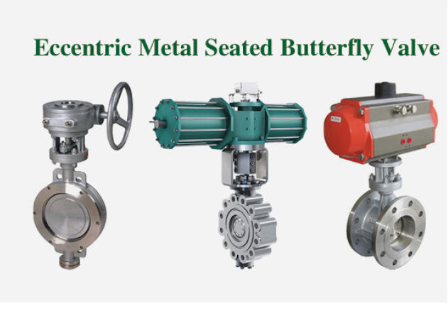
Types of Butterfly Valves
Mechanical arrangements range from simple concentric resilient-seated valves to double-offset and triple-offset metallic units. The physical connection between the valve and the adjacent piping directly dictates field servicing accessibility, mechanical stability, and joint integrity. Matching the physical properties of the valve with the hydraulic demands of the piping network establishes stable flow modulation across process systems.
Operating Principles and Quarter-Turn Mechanics
Butterfly valves operate on a quarter-turn mechanism where a circular disc rotates ninety degrees within the pipe bore to obstruct or permit fluid passage. When the valve is fully open, the disc aligns parallel to the fluid flow, allowing media to travel along both faces of the plate. When turned perpendicular to the flow path, the perimeter of the disc meets the internal valve seat to close the conduit.
The central shaft, or stem, penetrates the valve body to support and rotate the disc. Unlike gate or globe valves that retract their closing elements out of the pipeline bore, the disc of a butterfly valve remains permanently immersed within the process stream. This permanent presence creates an inherent restriction to fluid flow that introduces a slight localized pressure drop across the installation.
Because the wetted part directly contacts the fluid while in an open position, component materials must resist the chemical and physical properties of the fluid. The compact body profile requires considerably less installation envelope and mechanical support than bulkier gate valves or multi-turn globe valves. Operators can achieve rapid shutoff through a quarter-turn rotation, providing fast cycling during process emergencies or standard isolation routines.
Because the valve disc remains positioned in the pipeline bore even when fully opened, downstream pipe systems must accommodate continuous contact between process fluids and internal valve hardware.
During partial opening cycles, process fluid splits around the leading and trailing edges of the disc plate. This splitting creates dual flow channels that induce turbulence, shear forces, and rotational vortices directly behind the closing element. Understanding these internal fluid dynamics helps piping engineers evaluate whether a specific quarter-turn mechanism suits simple isolation or steady throttling service.
Concentric Butterfly Valve Design and Performance
Concentric butterfly valves represent the most straightforward mechanical configuration used in low-pressure and low-temperature process piping. In this design, the valve stem centers precisely in the middle of the valve disc and follows the exact centerline of the pipe bore. The resilient seat lines the entire inner circumference of the valve body, isolating the metal body from direct exposure to fluid media.
Because the disc and stem sit on the geometric center of the bore, the disc edge maintains significant interference friction against the seat during operation. The disc may contact the seat as early as 85 degrees of the way through the ninety-degree turn from full open to full close. This prolonged mechanical rubbing produces steady wear along the seat elastomer throughout repeated open and close sequences.
These units function primarily in utility water, low-pressure air, fire protection systems, and non-demanding fluid distribution networks. The simple geometric arrangement allows for economical fabrication and rapid seat renewal when wear develops. However, the continuous rubbing limits the maximum operational cycle frequency and restrains application boundaries to moderate operating pressures and temperatures.
Advantages
- Lower initial fabrication cost compared to multi-offset designs.
- Resilient body lining protects exterior metal from corrosive fluids.
- Bi-directional sealing capabilities in basic low-pressure configurations.
Limitations
- Significant disc-to-seat friction across the final travel arc.
- Limited compatibility with elevated system temperatures.
- Elastomer wear accelerates under frequent cycling conditions.
The continuous mechanical contact between the disc edge and the resilient seat during the closing stroke requires higher seated torque to complete shutoff. Operating staff must verify that actuation hardware provides adequate rotational force to overcome this interference profile. In clean liquid services with modest operating pressures, concentric valves deliver reliable bubble-tight shutoff at an economical procurement point.
Single, Double, and Triple Offset Configurations
Eccentric valve designs incorporate physical offsets in the shaft and disc geometry to minimize seal friction and extend operational longevity. Shifting the stem axis away from the disc face and the bore center alters the path of the sealing edge during rotation. These structural variations determine the exact angle where sealing contact occurs and establish the pressure containment boundaries of the assembly.
Single-offset butterfly valves feature a stem positioned directly behind the centerline of the sealing disc. This single spatial offset causes the disc to swing into the seat with an eccentric motion, delaying seat contact until later in the closing stroke. Because rubbing duration decreases compared to concentric styles, seat service life improves; however, single-offset valves remain relatively uncommon because double-offset geometry provides greater functional advantages without significant manufacturing cost penalties.
Double-offset butterfly valves, frequently designated as high-performance valves, incorporate two distinct design offsets. The first offset positions the stem behind the disc plane, while the second offset shifts the stem axis away from the pipe bore centerline. This combined geometry creates a camming action where the disc contacts the seat for only 1 to 3 degrees of the ninety-degree rotation, dramatically reducing seal wear and seating torque requirements in higher-pressure pipelines.
| Offset Category | Stem Positioning | Seat Contact Arc | Primary Operational Profile |
| Concentric | Centerline | Up to 85° | Best suited for basic utility distribution and low-pressure piping systems. |
| Single Offset | Behind Disc | Delayed Arc | Provides reduced seat friction but is rarely chosen over double offset styles. |
| Double Offset | Two Offsets | 1° to 3° | Optimized for high-pressure industrial processes and automated flow regulation. |
| Triple Offset | Three Offsets | Final Point | Constructed for severe industrial service, extreme heat, and tight metal sealing. |
Triple-offset butterfly valves add a third geometric offset in the sealing cone profile of the disc and seat interface. In addition to the shaft being shifted behind the disc and off-center, the conical seating surfaces are machined at an inclined angle. This cone-in-cone geometry eliminates sliding friction entirely, allowing the disc to engage the metal seat as a mechanical wedging contact only at the final point of closure.
The elimination of rubbing makes triple-offset configurations well suited for severe industrial operations involving extreme temperatures, superheated steam, and volatile chemicals. These assemblies accommodate tight metal-to-metal shutoff without relying on soft elastomeric compounds that degrade in harsh operating environments. Because precision machining is mandatory, triple-offset valves are more expensive and are constructed from premium structural alloys.
Valve Body and Component Material Selections
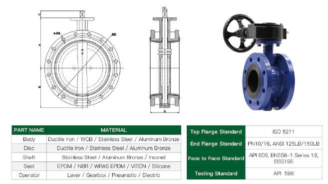
Selecting suitable body and trim materials determines how well a butterfly valve withstands fluid corrosion, mechanical fatigue, and thermal stress. The structural housing bears pipeline mechanical stresses, pressure containment loads, and thermal expansion forces transmitted from adjacent flanged connections. Specifying appropriate metallurgy prevents premature structural degradation and supports mechanical integrity throughout plant operating campaigns.
Carbon steel serves as the most widespread housing material across power generation, petrochemical distribution, and non-corrosive manufacturing utilities. It provides high tensile strength, excellent resistance to internal pressure, and favorable structural ductility at an economical price point. In general utility systems where process media presents minimal corrosive aggressiveness, carbon steel housings deliver predictable mechanical service.
Stainless steel housings and internal trims are specified for chemically aggressive process media, food processing, pharmaceutical production, and cryogenic lines. Alloys such as 316 stainless steel resist pitting corrosion from chlorides, prevent process media contamination, and maintain impact strength across wide thermal spectrums. For extremely corrosive environments like offshore marine platforms and desalination plants, exotic materials like titanium or super duplex stainless steel provide robust resistance against raw seawater erosion.
- Carbon steel provides economical pressure containment in low-corrosion process piping networks.
- Stainless steel delivers essential corrosion resistance and sanitary purity in chemical and refining processes.
- Titanium and specialized nickel alloys endure aggressive chlorides, seawater, and severe marine operating environments.
- Ductile iron offers an economical casting option for municipal water treatment and building utility loops.
- Super duplex stainless steel withstands high-pressure sour gas streams and severe offshore chemical service.
Internal trim components, including the valve disc, stem shafts, and retaining pins, frequently require higher-grade alloys than the external housing. The disc experiences continuous exposure to fluid velocity, cavitation shear, and chemical corrosion in the pipeline core. The stem must resist intense torsional loads delivered by actuators while preventing galling against internal body bushings and packing glands.
Resilient, Plastic, and Metal Sealing Options
The valve seat represents the primary wear component responsible for establishing bubble-tight isolation across the closed disc face. Seat materials must be selected based on chemical compatibility with the process fluid, operating line temperatures, and mechanical resistance to particulate abrasion. Seat formulations fall into three primary industrial categories: rubber-lined elastomers, engineered plastics, and precision-machined metal alloys.
Rubber-lined seats utilize vulcanized or bonded elastomers such as EPDM, NBR (nitrile), or FKM (fluoroelastomer) fitted directly within the housing cavity. These resilient seats compress under disc contact to form an effective seal across low-pressure and low-temperature fluid lines. They perform well in clean water distribution, air handling, and non-abrasive fluid applications, but soften and degrade when exposed to aggressive organic solvents or high operating heat.
Plastic-lined seats incorporate fluoropolymers like PTFE or PFA to handle aggressive industrial chemical environments. These engineered polymers resist broad chemical exposure, prevent process contamination, and provide smooth surfaces that lower operational turning torque. Plastic seats are common in chemical manufacturing, pharmaceutical processes, and abrasive slurry lines where elastomer formulations deteriorate.
Rubber-Lined
Elastomer seats like EPDM and NBR provide bubble-tight sealing in low-temperature utility water lines.
Plastic-Lined
PTFE and PFA polymer seats deliver broad chemical inertness and high purity in corrosive chemical services.
Metal-Seated
Precision-machined metal rings withstand extreme operating temperatures, abrasive media, and high-pressure steam.
Metal seats provide the mechanical robustness needed for high-pressure, abrasive, and high-temperature operating conditions. Constructed from stainless steel, Stellite, or inconel alloys, metal seating rings resist wire-drawing, erosion from suspended particulates, and thermal breakdown. While metal-seated designs demand higher manufacturing investment and require greater seating torque, they provide dependable process isolation under severe industrial operating conditions.
Wafer vs Lug and Double-Flanged Mounting Connections
Butterfly valves connect to surrounding pipeline flanges through four standard body styles: wafer, lug, semi-lug, and double-flanged configurations. The body design governs structural support, field bolting requirements, pipeline weight distribution, and overall maintenance convenience. Piping designers evaluate these connection formats to match facility layout constraints and future system maintenance procedures.
Wafer butterfly valves feature a slender, compact body profile designed to sandwich directly between adjacent pipe flanges. The assembly uses long threaded studs that span the complete width of the valve body, connecting the upstream and downstream flanges together. Alignment lugs or through-holes cast into the wafer body guide the bolts to center the disc inside the pipe bore.
While wafer designs offer reduced weight, compact dimensions, and lower purchasing costs, they present operational drawbacks during system servicing. Because through-bolts compress the valve body between both pipe flanges, servicing a wafer valve requires depressurizing and draining both adjacent piping sections. Removing the valve breaks the mechanical integrity of the entire pipe spool, preventing isolated downstream system maintenance.
Wafer Style Bodies
- Lower weight and compact face-to-face dimensions.
- Economical purchase cost for budget-conscious piping layouts.
- Through-bolts pass completely outside the valve body.
- Requires total system shutdown for inline servicing.
- Cannot serve as a dead-end terminal isolation point.
Lug Style Bodies
- Threaded female lugs accept individual bolts from each side.
- Enables dead-end service and downstream pipe removal.
- Allows localized system maintenance without draining upstream lines.
- Operates at slightly reduced pressure in dead-end service.
- Heavier metal body casting increases component weight.
Lug-style butterfly valves incorporate threaded metal lugs projecting around the outer perimeter of the valve housing. Flange bolts thread directly into the tapped lugs from each side of the pipeline rather than running through continuous long studs. This structural arrangement allows either side of the piping network to be disconnected while the opposite flanged joint remains pressurized and secured.
The ability to operate in dead-end service makes lug valves a dependable choice for isolation manifolds and pump discharge lines. Field technicians can remove downstream pipe segments for pump replacement or cleaning while the valve holds upstream system head pressure. However, because line stresses concentrate across the individual threaded lugs, dead-end pressure ratings are often lower than ratings for sandwiched wafer assemblies.
Semi-lug and double-flanged bodies represent specialized connection configurations for targeted industrial piping needs. Semi-lug bodies feature a combination of through-holes and tapped lugs, providing quick alignment in temporary or low-pressure lines. Double-flanged butterfly valves incorporate integral flanges with standard bolt hole patterns on both faces, providing strong structural stability and clear visual inspection access across high-diameter pipelines.
Manual, Gearbox, and Automated Valve Actuation
Actuating a butterfly valve requires sufficient rotational torque to overcome internal seat friction, bearing resistance, and fluid dynamic drag. The operating mechanism must position the disc accurately against moving process media while resisting flutter caused by localized turbulence. Valves operate through three primary mechanisms: direct manual hand levers, manual gearboxes, or automated pneumatic and electric actuators.
Manual hand levers offer quick quarter-turn operation for small-diameter valves operating under moderate pipeline pressures. A quarter-turn of the lever swings the disc between fully open and fully closed positions, with a notched locking plate holding intermediate throttle angles. While hand levers provide direct mechanical feedback, sudden manual operation can create severe fluid pressure spikes, and high line pressures can overwhelm manual leverage.
Manual gearboxes utilize worm gear mechanisms to multiply operator torque on medium and large valve assemblies. The gear reduction requires multiple turns of a handwheel to rotate the disc ninety degrees, substantially reducing manual physical exertion. This mechanical advantage eliminates the danger of sudden slamming, facilitating controlled operation against high differential line pressures while protecting adjacent piping from water hammer.
Manual Hand Lever
Provides fast quarter-turn actuation and immediate visual confirmation of disc position on compact low-torque valve assemblies.
Mechanical Gearbox
Reduces required operating torque through worm gearing, allowing safe, controlled positioning on large-diameter high-pressure valves.
Pneumatic Actuator
Delivers high rotational power and fast automated stroke speeds, functioning reliably in hazardous processing environments.
Automated pneumatic and electric actuators provide dependable torque for remote control loops, large valves, and hazardous installations. Pneumatic actuators utilize plant instrument air against pistons or elastomeric diaphragms to generate rapid, dependable quarter-turn positioning. Electric motor actuators incorporate precision gear trains and electronic feedback controls to manage steady, automated modulation across building automation and industrial process networks.
Automated packages frequently incorporate valve positioners, limit switches, and solenoid pilot valves to communicate status to central industrial automation systems. Sizing automated actuators requires calculating peak break-away torque, running friction, and hydrodynamic closing forces generated by the fluid stream. Specifying actuators with appropriate safety margins helps prevent valve stalls during system startup surges or unexpected line pressure variations.
Throttling Behavior, Cavitation, and Flow Limitations
While butterfly valves function effectively for on-off isolation, their hydrodynamic profile makes them less suitable for precise throttling service across wide operating ranges. The obstruction presented by the disc plate within the flow stream alters downstream velocity profiles and pressure gradients. Operating butterfly valves at narrow opening angles creates high localized fluid velocities that can induce rapid mechanical degradation.
When throttled below thirty degrees of opening, the narrow annular gap between the disc edge and the body creates a sharp localized pressure drop. If the localized fluid pressure dips below the vapor pressure of the liquid, vapor bubbles form and violently collapse against metallic trim surfaces. This phenomenon, known as cavitation, causes severe surface pitting, noisy vibration, and structural damage to the disc and valve seat.
In high-velocity gas lines, improper throttling can induce choked flow conditions where mass flow rates plateau regardless of downstream pressure reductions. High dynamic fluid forces acting unevenly across the disc plate can also induce severe stem flutter and premature packing gland leakage. Piping engineers must evaluate fluid velocities, pressure drops, and expansion factors before deploying quarter-turn butterfly discs for continuous flow modulation.
Improper throttling of butterfly valves at low opening angles can generate cavitation, intense pipe vibration, and choked flow conditions that degrade valve components and adjacent piping.
To avoid cavitation damage, system operators should limit continuous throttling to the linear flow range of the valve, typically between thirty and seventy degrees of disc rotation. In slurry handling and particulate-laden flows, partial opening should be managed carefully to avoid concentrated erosion along the leading sealing edges. Where precise, wide-range flow modulation is required, alternative valve designs like globe valves or specialized V-port ball valves often deliver better performance.
Primary Industrial Use Cases and Media Handling
Butterfly valves operate across diverse industrial sectors due to their compact footprint, minimal weight, and fast cycle capabilities. Their narrow face-to-face dimensions allow them to fit into congested mechanical rooms, industrial skid units, and underground utility vaults where bulkier valve designs are impractical. From clean municipal water treatment to abrasive mineral extraction, these quarter-turn devices support essential fluid handling networks.
Hydroelectric power facilities utilize large-diameter butterfly valves as penstock emergency shutoff devices and turbine isolation units. Their relatively low pressure drop during wide-open operation allows large fluid volumes to pass with minimal hydraulic energy loss. In pneumatic power systems and gas distribution networks, fast-acting butterfly valves isolate blower discharges, manage low-pressure air lines, and balance ventilation ducts.
Process industries deploy specialized butterfly configurations across a wide spectrum of aggressive and non-corrosive media applications. Facilities handling chemical vacuum service, industrial cooling water towers, and utility gas lines utilize resilient and high-performance offset designs to maintain reliable fluid containment. In slurry transport and mining tailings lines, hardened discs and abrasion-resistant elastomer linings withstand the scouring action of suspended mineral solids.
- Hydroelectric power generation uses large-bore butterfly valves for penstock isolation and turbine shutoff.
- Cooling water loops and condenser systems rely on resilient-seated wafer valves for high-volume liquid circulation.
- Industrial vacuum services deploy high-performance double-offset valves to maintain dependable vacuum seals.
- Slurry transport and wastewater treatment operations utilize abrasion-resistant elastomer linings to handle abrasive solids.
- Bulk chemical transfer systems employ fluoropolymer-lined valves to resist chemical attack and media contamination.
- Pneumatic conveying and air distribution networks utilize lightweight wafer butterfly valves for rapid system balancing.
Thermal power generating plants and district heating networks use high-performance metal-seated butterfly valves to control steam and condensate lines. The compact design simplifies thermal insulation procedures compared to bulky bolted-bonnet gate valves. When configured with appropriate structural metallurgy and sealing components, butterfly valves provide dependable process isolation across demanding industrial installations.
Inspection Routines and Field Seat Replacement
Butterfly valves require relatively little ongoing maintenance compared to complex multi-turn rising-stem valves. The simplified structural design eliminates complex internal cavities, bonnet gaskets, and wedging guides that frequently collect debris in gate valves. Establishing consistent visual inspections and operational cycling procedures helps preserve mechanical performance across long operating lifecycles.
Routine visual inspections should examine the valve exterior, flanged joint bolting, stem packing seals, and external actuator linkages. Inspectors should check for signs of packing gland weeping, stem corrosion, loose mounting hardware, and paint degradation on carbon steel housings. Manual gearboxes are intrinsically lubricated and designed to be maintenance-free, but visual checks should confirm grease seal integrity and verify that mechanical limit stops remain properly positioned.
Valves that remain in stationary open or closed positions for extended periods should be exercised regularly to maintain seat compliance and clear scale buildup. The valve should be opened and closed every six months after active use to verify smooth mechanical movement. This periodic cycling clears accumulated line sediment from the seat interface and prevents internal stem bearings from seizing within housing bushings.
Opening and closing butterfly valves every six months after active use clears pipeline sediment from the seat and preserves the mechanical integrity of internal bushings and seals.
When internal leakage develops across a closed resilient-seated valve, field maintenance and seat replacement can often be performed without replacing the entire housing. Depending on manufacturer specifications, technicians can unbolt the valve from the piping, remove the retaining components, and withdraw the stem and disc. The worn elastomer or plastic seat can then be removed and a new factory replacement seat installed following the vendor’s assembly recommendations.
Frequently Asked Questions
What is the difference between wafer and lug butterfly valves?
Wafer valves sandwich between pipe flanges using long studs that pass through external alignment holes. Lug valves feature tapped metal lugs that accept individual bolts from each side, allowing for downstream piping removal and dead-end service.
Why are triple-offset butterfly valves used in high-temperature applications?
Triple-offset butterfly valves utilize an inclined conical sealing geometry that eliminates sliding friction between the disc and the seat. This mechanical design enables all-metal sealing components that withstand elevated temperatures and severe operating pressures without degrading.
Can butterfly valves be used for flow throttling?
Butterfly valves have poor throttling capabilities compared to dedicated control valves, particularly at low opening angles below thirty degrees. Restricting flow at narrow angles can induce cavitation, high fluid turbulence, stem flutter, and accelerated erosion across sealing surfaces.
How often should butterfly valves undergo operational cycling?
The valve should be opened and closed every six months after active use. Periodic operational cycling prevents stem binding, clears particulate accumulation from seating areas, and verifies proper actuator function.
What seat material is best for chemical and abrasive services?
Plastic-lined seats constructed from fluoropolymers like PTFE work well with chemical and abrasive media or where sanitary purity is essential. For high temperatures combined with abrasive wear, hardened metal-seated configurations provide durable performance.
Summary of Butterfly Valve Selection
Selecting the appropriate butterfly valve requires balancing operational line pressure, fluid temperatures, media corrosiveness, and pipeline mechanical layouts. Matching concentric, double-offset, or triple-offset disc geometries with compatible body connections and seating materials helps piping networks achieve reliable flow isolation. Systematic visual monitoring and regular six-month cycling preserve mechanical functionality and seat life across industrial installations.